©2021 Micro-Air corp. 6 rev. 1.06
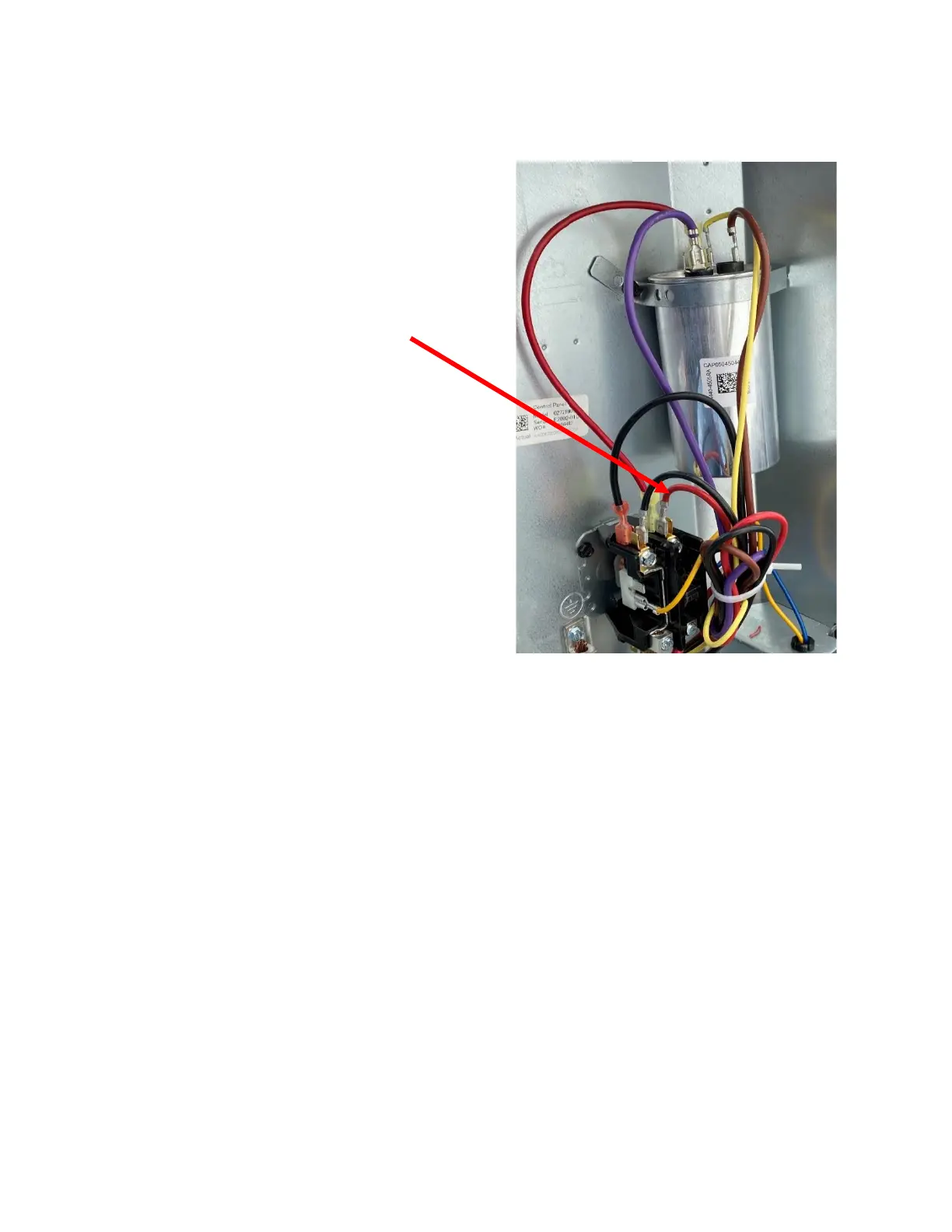
Step 7: Connecting the BROWN wire
Follow the wire that connects the C terminal on the run
capacitor to the contactor. Disconnect the compressor
“R” terminal wire located on the same side of the
contactor. This wire is often a heavy gauge wire
connected to the screw part of the contactor. It may
also be on a quick connect as shown in figure 5.
Connect the disconnected wire to the BROWN wire
from EasyStart. Connect only these two wires together
and not to anything else.
Step 8: Connecting the WHITE wire
Connect the EasyStart WHITE wire to the contactor where the wire was removed from in the last step.
This is typically under the screw terminal on the contactor.
Note: Compressors with an RLA over 18 amps should not use the spade connection like shown
in figure 5 but should connect using a ring, fork or direct wire connection under the screw. Be sure to
match whatever method is used for the original installation.
 Loading...