© 2011 Microchip Technology Inc. DS21137G-page 21
HCS300
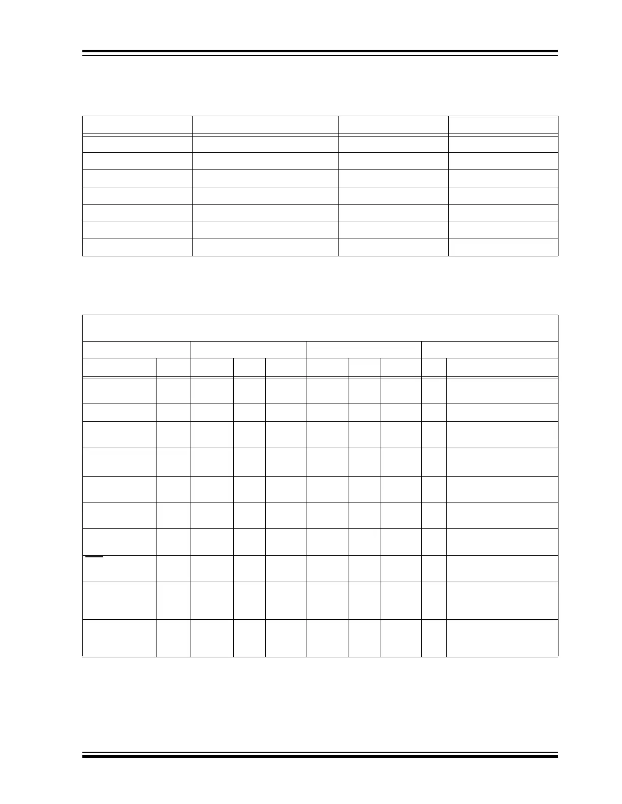
9.0 ELECTRICAL CHARACTERISTICS
TABLE 9-1: ABSOLUTE MAXIMUM RATINGS
TABLE 9-2: DC CHARACTERISTICS
Symbol Item Rating Units
V
DD Supply voltage -0.3 to 6.6 V
V
IN Input voltage -0.3 to VDD + 0.3 V
V
OUT Output voltage -0.3 to VDD + 0.3 V
I
OUT Max output current 50 mA
T
STG Storage temperature -55 to +125 °C (Note)
T
LSOL Lead soldering temp 300 °C (Note)
V
ESD ESD rating 4000 V
Note: Stresses above those listed under “ABSOLUTE MAXIMUM RATINGS” may cause permanent damage to
the device.
Commercial (C): Tamb = 0 °C to +70 °C
Industrial (I): Tamb = -40 °C to +85 °C
2.0V < VDD < 3.0 3.0 < VDD < 6.3
Parameter Sym. Min. Typ.
1
Max. Min. Typ.
1
Max. Unit Conditions
Operating cur-
rent (avg)
2
ICC 0.2 1 1.0 2.5 mA
V
DD = 3.0V
VDD = 6.3V
Standby current
ICCS 0.1 1.0 0.1 1.0 μA
Auto-shutoff
current
3,4
ICCS 40 75 160 650 μA
High level Input
voltage
V
IH 0.55VDD VDD+
0.3
0.55VDD VDD+
0.3
V
Low level input
voltage
V
IL -0.3 0.15VDD -0.3 0.15VDD V
High level output
voltage
V
OH 0.6VDD 0.6VDD V
I
OH = -1.0 mA VDD = 2.0V
I
OH = -2.0 mA VDD = 6.3V
Low level out-
put voltage
V
OL 0.08VDD 0.08VDD V
I
OL = 1.0 mA VDD = 2.0V
IOL = 2.0 mA VDD = 6.3V
LED
sink
current
5
ILED 1.0 1.8 2.5 2.0 2.7 3.7 mA
V
LED
6
= 1.5V VDD = 3.0V
V
LED
6
= 1.5V VDD = 6.3V
Pull-down
Resistance;
S0-S3
R
S0-3 40 60 80 40 60 80 kΩ
V
DD = 4.0V
Pull-down
Resistance;
PWM
R
PWM 80 120 160 80 120 160 kΩ
V
DD = 4.0V
Note 1: Typical values are at 25 °C.
2: No load.
3: Auto-shutoff current specification does not include the current through the input pull-down resistors.
4: These values are characterized but not tested.
5: With V
LOW Sel = 0 for operation from 2.0V to 3.0V and VLOW Sel = 1 for operation from 3.0V to 6.3V.
6: V
LED is the voltage drop across the terminals of the LED.