www.microchip.com/icd4
ADDITIONAL INFORMATION
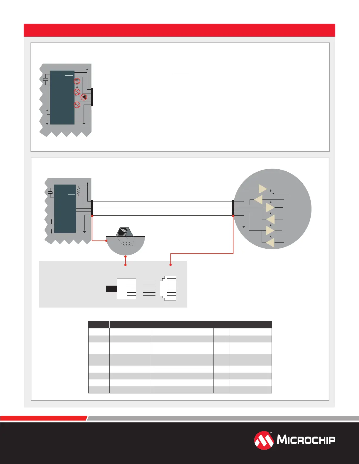
Target Circuit Design Precautions
• Do not use greater than 100 µF capacitance on Vdd: Depending on the overall load, it will
prevent the target from powering quickly when MPLAB ICD 4 is the source of power.
• Do not use capacitors on MCLR: They will prevent fast transitions of Vpp.
• Do not use multiplexing on PGC/PGD: They are dedicated for communications to
MPLAB ICD 4.
• Do not use capacitors on PGC/PGD: They will prevent fast transitions on data and
clock lines during programming and debug communications.
• Do not use diodes on PGC/PGD: They will prevent bidirectional communication
between MPLAB ICD 4 and the target PIC
®
MCU.
• Do not exceed recommended cable lengths: Refer to the Hardware Specication of
the MPLAB ICD 4 online help or user's guide for cable lengths.
2
1
5
4
3
Target V
DD
(tVDD)
Target Application PC Board
V DD
PGC
PGD
V
SS
AVDD**
AVSS**
XTAL*
VPP /MCLR
Target Application
Device
V
Circuitry and Connector Pinouts
2
1
5
4
3
Target V
DD
(tVDD)
50 kΩ
Typical
Target Application PC Board
V DD
PGC
PGD
V
SS
AVDD**
AV
SS**
XTAL*
tVDD
MPLAB
®
ICD 4
Internal Circuitry (simplified)
V
PP
Correct
VPP /MCLR
Target VDD
(tV
DD
) is used
to power the
input/output
drivers in the
MPLAB ICD 4
debugger
tV
DD
tVDD
tVDD
tVDD
Typical cable length is 6 inches
Target Application
Device
* MPLAB ICD 4 is controlled by a 32-bit MCU with an Arm
®
Cortex
®
-M7 core.
** Target device must be running with an oscillator for the debugger to function
as a debugger.
*** If the device has AVdd and AVss lines, they must be connected for the
debugger to operate.
RJ-11 to RJ-45 Pinouts
Pin RJ-11 Function Pin RJ-45
JTAG Test Mode Select 1 TMs
1 Reserved 2
2 PGC (ICSPCLK)
Standard Com Clock/
TCK (JTAG Test Clock)
3 PGC (ICSPCLK)
3 PGD (ICSPDAT)
Standard Com Data/
TDO (JTAG Test Data Output)
4 PGD (ICSPDAT)
4 GND Ground 5 GND
5 V
dd_TGT Power On Target 6 Vdd_TGT
6 V
pp Power 7 Vpp
JTAG Test Data Input 8 TDI
The modular cable with the
RJ-11 connector attaches
to the RJ-45 socket on the
MPLAB ICD 4.
RJ-11 Connector/Cable RJ-45 Socket
123456
At Target
Bottom View
Of Target Board
2 4 6
1 3 5
 Loading...


