2
Pencil Line
Front
Rear
1
5
”
3”
4 1/8”
1/2”
MDF
Installation Procedure
These procedures are for use with a standard 10” diameter with either 1/8” kerf or Thin Kerf saw blade depends on the
model you purchased. Please follow the exact order of steps and sequences.
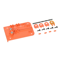
Step 1 (for both models) - Prepare a Setup Board
Prepare a Setup Board from a 1/2" thick man-made sheet stock (preferably 1/2" MDF) - 15" L x 4-1/8" W.
The front edge must be 90˚ to the long edges. Draw a pencil line across the width that is 3" from the rear
end.
Note: Better grade 1/2” plywood with no void can also be used - it must be flat and dimensionally stable.
Step 2 (for both models) - Create a Saw Kerf on the Setup Board
1) Set the saw blade at 1/4" above the top surface of the setup board. Be sure the table saw top is clean and free from sawdust
and other debris.
2) Secure the rip fence at 2” to the right of and parallel to the saw blade.
IMPORTANT: Keep the rip fence locked in position until the installation is complete.
The saw kerf that you are going to create in the next step will be the alignment path for the Drill Guide. It is extremely important that the
saw kerf is parallel to the right edge of the Setup Board. Using the GRR-Ripper® for this ripping procedure is the best way to ensure a
parallel cut.
3) Feed the Setup Board through the saw blade and stop at the pencil line.
4) Turn off the saw motor while maintaining firm pressure on the GRR-Ripper®, and wait until the saw blade comes to a com-
plete stop.
Model SP-0125
1/8” Kerf Splitter - Green
Follow drawings under here Ð
Model SP-0100TK
Thin Kerf Splitter - Yellow
Follow drawings under here Ð
Line up carbide
tooth with
alignment mark.
Line up carbide
tooth with
alignment mark.
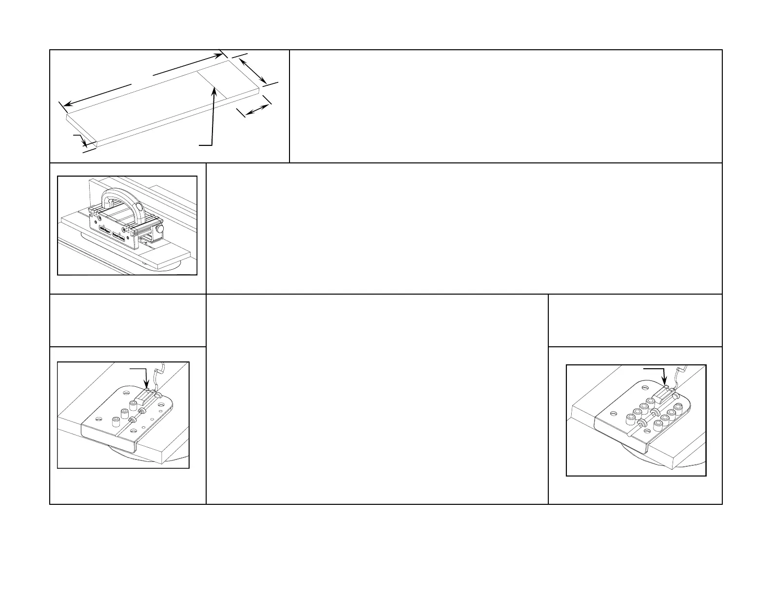
Step 3 - Establish the Guide Hole Distance from the Saw Blade
1) Disconnect the power to the table saw.
2) Pull back the Setup Board so the saw blade (without stiffener) can be raised to
its maximum height within the saw kerf.
3) Place the bottom center rib of the Drill Guide into the saw kerf and push the
Drill Guide toward the saw blade until its cheek comes in contact with the front
edge of the Setup Board, and one of the carbide teeth becomes engaged in the
front opening of the Drill Guide. Align that tooth with the alignment mark on the
Drill Guide’s opening. Make sure that all guide holes are still within the ZCI. This
will establish the distance of the guide holes behind the saw blade when it is fully
raised.
Note: The Drill Guide’s opening may be wider than your saw blade, this is normal. MJ
Splitter is not designed to align to the center behind the saw blade.
Remaining installation steps are similar for both models of the
MJ Splitter - slight differences can easily be observed in their
drawings with annotations.
 Loading...