3
Model SP-0125
1/8” Kerf Splitter - Green
Follow drawings under here Ð
Model SP-0100TK
Thin Kerf Splitter - Yellow
Follow drawings under here Ð
Hold –down
Clamp
P
r
e
s
s
u
r
e
n
e
x
t
t
o
D
r
i
l
l
G
u
i
d
e
o
n
l
y
.
R
i
p
F
e
n
ce
Micro Jig ZeroPlay™
Guide Bar Stop
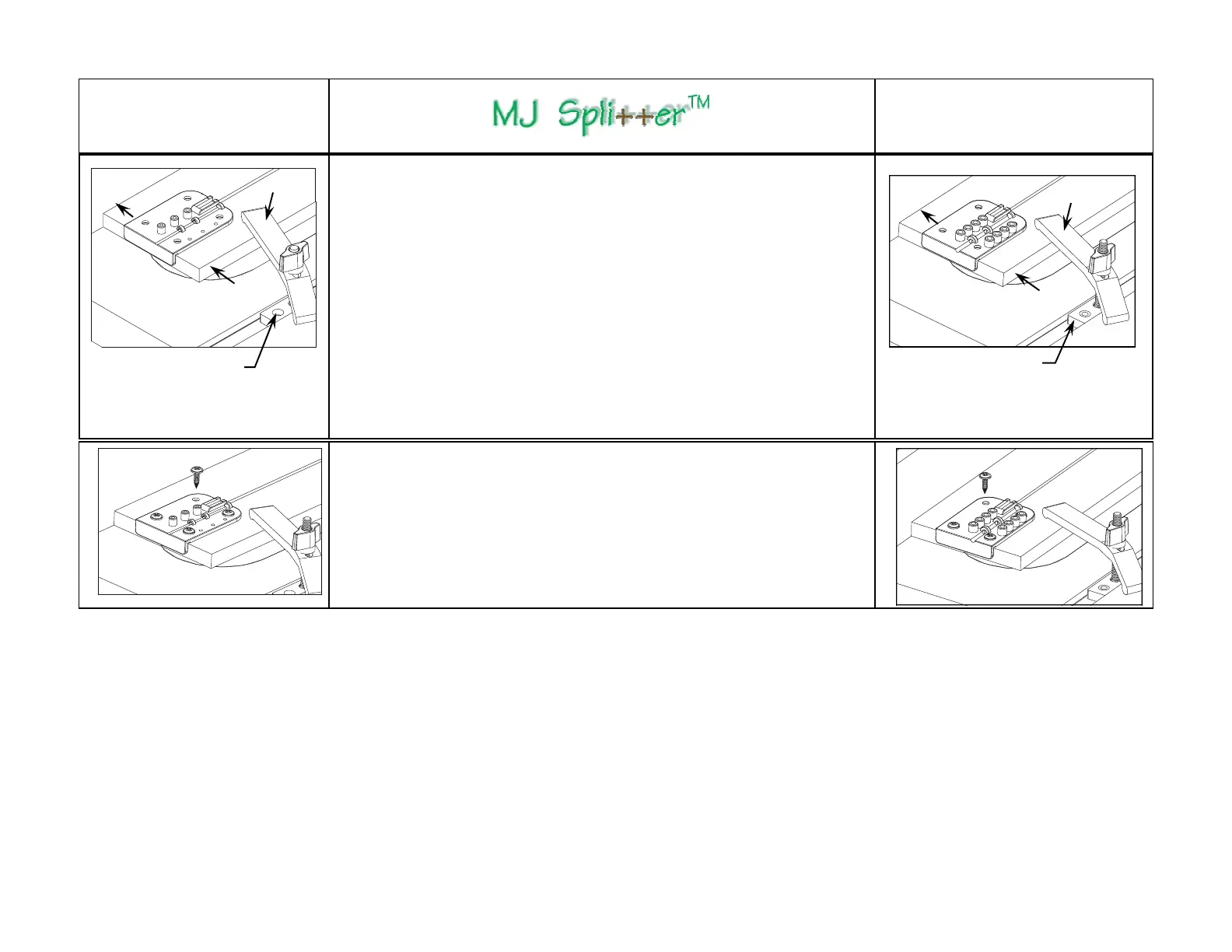
Step 4 - Securing the Setup Board
1) Lower the saw blade just below the Setup Board top surface without altering
the position of the Setup Board and the Drill Guide.
2) Clamp the Setup Board in position while applying firm finger or light feather
board pressure on the Setup Board against the fence so that the Drill Guide is
tight in the saw kerf. This ensures that the right edge of the bottom rib on the
Drill Guide is in full contact with the right edge of the saw kerf. This will also
align the centers of the guide holes at the pre-determined distance from and
parallel to the right edge of the saw kerf, regardless of the actual width of the
saw kerf. (Vibration will inevitably cause the saw kerf to be slightly wider than
the width of your saw blade.)
Note: The illustration shows a fast and simple way of clamping the Setup
Board by using a Hold-Down Clamp and the Stop from Micro Jig’s ZeroPlay™
Guide Bar System. You may also clamp a board bridged over the Setup Board
from the edge of your table saw top.
Hold –down
Clamp
R
i
p
F
e
n
ce
Micro Jig Zero-
Play™ Guide Bar Stop
P
r
e
s
s
u
r
e
n
e
x
t
t
o
D
r
i
l
l
G
u
i
d
e
o
n
l
y
.
R
i
p
F
e
n
c
e
Step 5 - Securing the Drill Guide
1) Secure the Drill Guide onto the Setup Board using (4) #8 x 1/2" wood screws
(provided). Pilot holes are not required if you use a power hand drill (the bottom of
the screw holes are countersunk to accommodate any swarf from the drilling opera-
tion). DO NOT drive the screws all the way with the power drill to prevent stripping
the threads - lightly tighten the screws with a Robertson or Phillips screwdriver.
2) If you prefer pilot holes, use a 1/8” drill bit to drill the pilot holes NOT MORE than
1/8" deep, and lightly tighten the screws by hand.
 Loading...