4
Model SP-0125
1/8” Kerf Splitter - Green
Follow drawings under here Ð
Model SP-0100TK
Thin Kerf Splitter - Yellow
Follow drawings under here Ð
R
i
p
F
e
n
ce
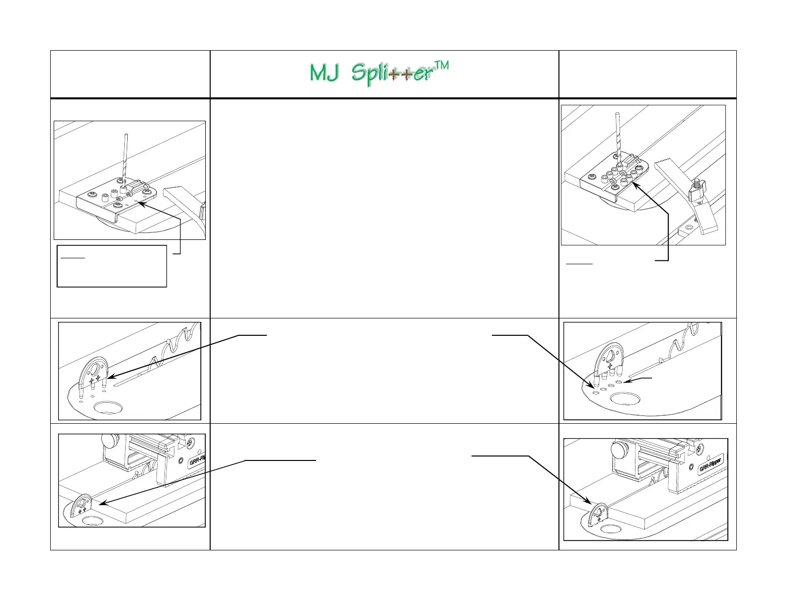
Do not drill the storage
holes onto the MDF in this
step, drill them in Step 9.
Step 6 - Drilling the Splitter Location Holes
1) Make sure the Drill Guide is secured on the Setup Board and that there is no de-
bris or gap between them. The guide holes must be perpendicular to the Setup
Board. Now, lower the saw blade completely to avoid drill bit contact.
2) Chuck the provided drill bit into a power hand drill and carefully line up the drill
with one of the guide holes. Hold the hand drill as perpendicular and steady as pos-
sible and drill through the guide hole to make that MJ Splitter location hole on the
ZCI.
IMPORTANT: Drill each hole in one single quick and continuous motion. DO NOT
stop and go or re-drill the same hole, as this will enlarge the MJ
Splitter
location
hole and the guide hole, thus resulting in a loosely fitting MJ Splitter.
3) Drill the remaining holes in the same manner.
Note: The pins on the MJ Splitters are 3/8” in length. Preferably, drill through holes
on the ZCI. If your ZCI uses replaceable blanks thinner than 3/8” and has a metal
frame under the required hole locations, the pins of the MJ Splitters need to be
shortened accordingly. If your ZCI is made out of hard plastic or other material that
does not “give,” e.g., phenolic or solid surface material, you may need to ream the
location holes lightly with the same provided drill bit.
4) Countersink the mounting holes on the ZCI about 1/32” deep on Thin Kerf model,
this provides relief for the radius edges on the pins.
Do not drill through
the storage holes on
the Thin Kerf model.
R
i
p
F
e
n
c
e
R
i
p
F
e
n
c
e
R
i
p
F
e
n
c
e
1/32” deep
countersink
Step 7
Push the MJ Splitter completely down - by hand only -
so that it fits tightly in the holes.
Dip the pins in wax if the fit is very tight.
Step 8
MJ Splitter is ready for use with
or without the
GRR-Ripper®.
To remove, insert a screwdriver
through the hole and pull upward
with slight thumb pressure on the
top center of the splitter.
 Loading...