9
•The supply line should now be drained. Use a
battery powered or properly grounded drill to
avoid shock hazard.
•Drill a
3
/
16
" hole in the supply line; (do not
drill through the opposite wall).
•Turn the handle to expose the lance no more
than
3
/
16
" beyond the rubber gasket.
•Place the body of the valve over the hole so
that the lance fits into the hole.
•Assemble and tighten the brass screw.
•Turn the Valve Handle clockwise (inward)
until firmly seated. The valve is closed.
3. With the Feed Water Saddle Valve closed,
open the sink faucet and the water supply and
allow the water to run for a few minutes to
flush any debris caused by the installation.
•Close the faucet and check the Feed Water
Saddle Valve for leaks.
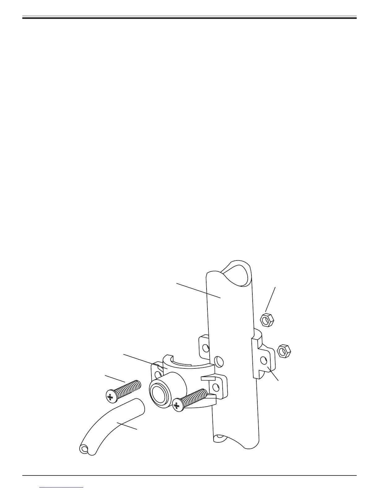
C. Drain Clamp Installation
Choose the drain outlet location per Sec. III, C.5,
page 7.
The following are instructions for discharging into
the sink drain pipe. (Refer to Fig. 1, page 3.)
1. Position the Drain Clamp on the sink drain
pipe above the drain trap. Allow room for
drilling. Tighten securely.
2. Use a battery powered or properly grounded
drill. Using the Clamp port as a drill guide,
drill a
7
/
32
" hole through the wall of the drain
pipe. Do NOT penetrate the opposite side of
the pipe.
3. Locate the
3
/
8
" Black Drain Tubing which is
shipped loose in the box.
NOTE: When cutting the polytubing make
clean, square cuts, failing to do so could result
in poor connections and possible leaks.
NOTE: The lowest point of the line should be
the point of connection to the Drain Clamp.
There should be no sag in the line as this may
cause excessive noise as the reject water is
flowing to drain.
Firmly press one end of the tubing over the
3
/
8
" drain outlet hose barb on the Air Gap
Faucet. Allow the tubing to relax, then press
firmly again to insure proper seating. No
connectors are required when attaching hose
Drain Clamp
Front Plate
Drain Pipe
1/4" Nut
1/4" Screw
Drain Clamp
Back Plate
Black Drain Tubing
3/8" DRAIN CLAMP ASSEMBLY
Figure 4