EasyManua.ls Logo

Micromark MM23207 - User Manual

Micromark MM23207
12 pages
Print Icon
To Next Page IconTo Next Page
Loading...
INSTALLATION & OPERATING INSTRUCTIONS
IIMMPPOORRTTAANNTT:: PPLLEEAASSEE RREEAADD TTHHEESSEE IINNSSTTRRUUCCTTIIOONNSS CCAARREEFFUULLLLYY BBEEFFOORREE AATTTTEEMMPPTTIINNGG TTOO IINNSSTTAALLLL TTHHIISS AALLAARRMM SSYYSSTTEEMM..
IIFF TTHHEE SSYYSSTTEEMM IISS BBEEIINNGG IINNSSTTAALLLLEEDD BBYY AA SSEECCUURRIITTYY IINNSSTTAALLLLEERR OORR EELLEECCTTRRIICCAALL EENNGGIINNEEEERR,, PPLLEEAASSEE EENNSSUURREE TTHHAATT AA
CCOOPPYY OOFF TTHHEESSEE IINNSSTTRRUUCCTTIIOONNSS IISS GGIIVVEENN TTOO TTHHEE CCUUSSTTOOMMEERR FFOORR RREETTEENNTTIIOONN AANNDD FFUUTTUURREE RREEFFEERREENNCCEE..
This alarm system can provide valuable protection for your home and property if used properly. However, the system cannot
guarantee complete protection against burglary or robbery. Therefore, the manufacturer, distributor or supplier will not be
held responsible for any loss or damage which may occur.
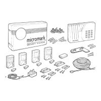
6-ZONE EASYFIT INTRUDER ALARM
Check the contents of the
packaging:
1x6 zone control panel
External siren
9V PP3 alkaline back up
system battery
Mains adaptor
4 PIR sensors
2 sets of hardwired door
contacts
8 sticky pads
Fixing screws
Cable clips
Wall plugs
Screwdriver (fits PIR cover
screws)
50m of multi-core alarm
cable
Fixing bracket
IMPORTANT
In certain areas of the country you are required by law to
notify the Police and Local Authority when you install an
Alarm System. Since the requirements of each Authority
differ, we suggest that you contact the Environmental Officer
of your local Borough for full information about your local
area‘s by-laws.
Please note that this equipment and its components have NO user serviceable parts.
If you experience any difficulties call our Helpline.
MMIICCRROOMMAARRKK HHEELLPPLLIINNEE TTEELL:: 00887700 224411 33002299
Monday to Friday (8.30am to 5pm)
www.micromark.co.uk
CCOONNTTEENNTTSS
Planning your system . . . . . . . . . . . . . . . . . . . . . . . . . . . . . . . . .2
Wiring diagrams . . . . . . . . . . . . . . . . . . . . . . . . . . . . . . . . . . . . .3
Start with installing the control panel and siren . . . . . . . . . . . .4
Fitting PIRs and door contacts . . . . . . . . . . . . . . . . . . . . . . . . . .6
Wiring the control panel . . . . . . . . . . . . . . . . . . . . . . . . . . . . . . .7
Control panel status . . . . . . . . . . . . . . . . . . . . . . . . . . . . . . . . . .8
Total immobilisation of system . . . . . . . . . . . . . . . . . . . . . . . . . .8
Checking the system – Walk test . . . . . . . . . . . . . . . . . . . . . . . .8
Checking the system – Bell test mode . . . . . . . . . . . . . . . . . . . .8
System entry time . . . . . . . . . . . . . . . . . . . . . . . . . . . . . . . . . . . .9
System exit time . . . . . . . . . . . . . . . . . . . . . . . . . . . . . . . . . . . . .9
Bell reset . . . . . . . . . . . . . . . . . . . . . . . . . . . . . . . . . . . . . . . . . .10
To change password . . . . . . . . . . . . . . . . . . . . . . . . . . . . . . . .10
To arm the system . . . . . . . . . . . . . . . . . . . . . . . . . . . . . . . . . . .11
To disarm the system . . . . . . . . . . . . . . . . . . . . . . . . . . . . . . . . .11
Panic alarm . . . . . . . . . . . . . . . . . . . . . . . . . . . . . . . . . . . . . . . .11
Chime zone . . . . . . . . . . . . . . . . . . . . . . . . . . . . . . . . . . . . . . . .11
Part Guard . . . . . . . . . . . . . . . . . . . . . . . . . . . . . . . . .Back cover
Troubleshooting . . . . . . . . . . . . . . . . . . . . . . . . . . . . .Back cover
KKIITT CCOONNTTEENNTTSS
PPlleeaassee nnoottee:: BBeeffoorree yyoouu ssttaarrtt ttoo iinnssttaallll tthhiiss MMiiccrroommaarrkk AAllaarrmm,, wwee aaddvviissee tthhaatt yyoouu sshhoouulldd ttaakkee aaddeeqquuaattee ssaaffeettyy pprreeccaauuttiioonnss
wwhheenn uussiinngg ppoowweerr ttoooollss aanndd llaaddddeerrss.. PPrrootteecctt yyoouurr eeyyeess wwhheenn ddrriilllliinngg aanndd
nneevveerr
uussee aapppplliiaanncceess iinn ddaammpp oorr wweett ccoonnddiittiioonnss..
PIR SENSORS
MAINS ADAPTOR
DOOR
CONTACTS
ALARM CABLE
FIXING BRACKET
CONTROL PANEL
SIREN
www.ukpanels.com

Questions and Answers

  • K
    Kenneth ScottAug 2, 2025
    Why Micromark Security System will not arm?
    • T
      Taylor KellerAug 2, 2025
      If your Micromark Security System won't arm, it could be due to a continually lit red STATUS LED. Ensure the anti-tamper spring is fully depressed. Also, check the Red and Yellow connections at the siren terminals to make sure they are correctly connected.
  • T
    Tiffany KlineAug 8, 2025
    What to do if Micromark MM23207 Security System alarm activates immediately upon entry?
    • L
      Lisa SmithAug 8, 2025
      If the alarm on your Micromark Security System activates immediately upon entry, giving you no time to switch it off, it's likely that Zone 3 or 4 PIR is detecting you as you enter, or there is an intruder. If possible, relocate the PIR. Otherwise, address the potential intrusion issue.
  • M
    Mary CopelandAug 14, 2025
    How to fix a fault on my Micromark MM23207 panel with the LED illuminated?
    • B
      Brittany BaileyAug 14, 2025
      If your Micromark Security System panel is showing a fault with the LED illuminated, it might be due to the door contacts not being close enough (within 5mm). Try moving the contact magnet closer to resolve this issue.
  • P
    Pamela BruceAug 20, 2025
    What to do if I am unable to set Micromark Security System and the zone LED is illuminated?
    • V
      Veronica JonesAug 21, 2025
      If you are unable to set your Micromark Security System and a zone LED is illuminated, it's likely that a door is open or a PIR is being triggered by movement. Ensure all doors are closed and remain still while entering the password.
  • C
    Charlotte SanchezAug 27, 2025
    What to do if the Micromark MM23207 Security System internal alarm sounds when finishing programming?
    • S
      saramejiaAug 27, 2025
      If the internal alarm sounds on your Micromark Security System after finishing programming and pressing P0E, it could be due to the tamper spring on the panel not being depressed. Try tightening the wall screw and refitting the panel. Alternatively, there may be bad connections at the terminal block, so check those connections as well.

Summary

Planning Your System

What is a Zone?

Defines different protection zones within the alarm system.

Important Points to Consider

Key considerations before installing sensors and components.

Accessories

Details available optional accessories for the alarm system.

Wiring Diagrams

Typical Wiring Diagram for Zones

Illustrates standard wiring for PIRs and door contacts in zones.

Wiring PIRs and Door Contacts Separately

Shows how to wire sensors individually to the control panel.

Adding Extra Door Contacts

Demonstrates how to connect additional door contacts to a zone.

Installing the Control Panel and Siren

Control Panel Placement and Mounting

Guide to positioning, drilling, and fixing the control panel bracket.

Fitting PIRs and Door Contacts

PIR Sensor Installation

Instructions for preparing, wiring, and mounting PIR motion sensors.

Door Contact Installation

Steps for fitting, wiring, and marking door/window contacts.

Wiring the Control Panel

Control Panel Wiring Connections

Details connecting power, PIRs, and door contacts to the panel.

Battery and Anti-Tamper Spring

Covers installing the backup battery and the anti-tamper mechanism.

System Checks

Walk Test Procedure

Step-by-step guide to testing each zone's detection.

Bell Test Procedure

Procedure to test the audible siren and internal buzzer.

Control Panel Status Indicators

Explains the meaning of the control panel's POWER and STATUS LEDs.

Total System Immobilisation

Steps to reset the system if the password is lost.

System Timing Configuration

Setting System Entry Time

How to configure the delay time for entering the premises.

Setting System Exit Time

How to configure the delay time for leaving the premises.

System Configuration Options

Bell Reset Time Configuration

Adjusting the duration the siren sounds after activation.

Changing System Password

Procedure to set a new 4-digit user password for security.

System Operation Modes

Arming the System

Instructions on how to set the alarm system to the armed state.

Disarming the System

How to deactivate the alarm system using the password.

Chime Zone Functionality

Using zones to provide audible alerts on entry.

Panic Alarm Activation

How to manually trigger the alarm for emergencies.

Special Modes and Troubleshooting

Part Guard Mode

Arming the system while leaving specific zones inactive.

Troubleshooting Common Issues

Solutions for common problems encountered with the alarm system.

Micromark MM23207 Specifications

General IconGeneral
BrandMicromark
ModelMM23207
CategorySecurity System
LanguageEnglish

Related product manuals