Sensor adjustment with Teach-in procedure
Place object at position
Press push-button for about
3 s until LEDs flash
simultaneously
Press push-button for
about 1 s
Place object at position
Press push-button for about
3 s until LEDs flash
simultaneously
Place object at position
Press push-button for
about 1 s
Set two way reflective
barrier
Enable/disable Teach-in
push-button
Place object at position
Press push-button for about
3 s until LEDs flash
simultaneously
Press button for about 13 s
until LEDs flash
mutually
Press push-button for
about 10 s
To change output characte-
ristic press push-button
for about 1 s
While pressing the push-
button switch on power
supply
Keep push-button pressed
for about 3 s until both
LEDs flash simultaneously
flashes
on: push-button
enabled
off: push-button
disabled
To enable/disable Teach-in
press push-button
for about 1 s
While pressing the push-
button switch on power
supply
Keep push-button pressed
for about 13 s until both
LEDs stop
flashing
Operating Instructions
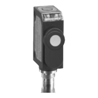
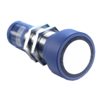
Ultrasonic proximity switch with
one switched output
zws-15/CD/QS zws-15/CE/QS
zws-24/CD/QS zws-24/CE/QS
zws-25/CD/QS zws-25/CE/QS
zws-70/CD/QS zws-70/CE/QS
Product Description
The zws sensor offers a non-contact
measurement of the distance to an
object which must be positioned
within the sensor’s detection zone.
The switched output is set in depen-
dence of the adjusted detect dis-
tance.
Via the push-button, the detect dis-
tance and operating mode can be
adjusted (teach-in). Two LEDs indi-
cate operation and the state of the
switched output.
Safety Notes
Read the operating instructions
prior to start-up.
Connection, installation and
adjustment works may only be
carried out by expert personnel.
No safety component in
accordance with the EU Machine
Directive
Proper use
zws ultrasonic sensors are used for
non-contact detection of objects.
Installation
Mount the sensor at the installa-
tion site with the aid of the
enclosed mounting plate.
Maximum torque: 0,5 Nm
Fig. 1: Attachment with mounting plate
Connect a connection cable to the
M8 device plug.
Avoid mechanical load on the con-
nector.
Fig. 2: Pin assignment with view onto sensor
plug and colour coding of the
microsonic connection cable
Start-Up
Connect the power supply.
Carry out the adjustment
in accordance with the diagram.
Factory Setting
Operation with one detect point
brown
blue
4
2
D
Sync
black
white
Switched output on NOC
Detect points at operating range
Operating modes
Three operating modes are available
for the switched output:
Operation with one detect point
The switched output is set if the ob-
ject falls below the set detect point.
Window mode
The switched output is set if the ob-
ject is within the set window mar-
gins.
Two-way reflective barrier
The switched output is set if the ob-
ject is between sensor and reflector.
Synchronization
You can synchronize as many sensors
as you like.
Apply a square-wave signal to the
sync-input with pulse width t
i
and
repetition rate t
p
(Fig. 3 and
technical data).
A high level on the sync-input will
deactivate the sensor.
Fig. 3: External synchronization signal
Checking operation mode
In normal mode shortly press the
push-button.
The green LED stops shining for one
second, then it will show the current
operating mode:
1 x flashing = operation with one
switching point
2 x flashing = window mode
3 x flashing = reflective barrier
After a break of 3 s the green LED
shows the output function:
1 x flashing = NOC
2 x flashing = NCC
Maintenance
microsonic sensors are maintenance-
free. In case of excess caked-on dirt
we recommend cleaning the white
sensor surface
Sensor disabled Sensor disabled
Start
+U
B
-U
B
t
i
t
p