Product description
Ԏ
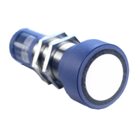
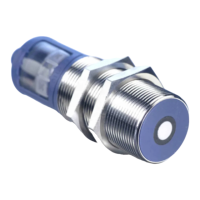
The mic+ sensor with one switching
output measures the distance to an
object within the detection zone
contactless. Depending on the ad-
justed detect distance the switching
output is set.
Ԏ
All settings are done with two push-
buttons and a three-digit LED-dis-
play (TouchControl).
Ԏ
Three-colour LEDs indicate the swit-
ching status.
Ԏ
The output functions are changea-
ble from NOC to NCC.
Ԏ
The sensors are adjustable manually
via TouchControl or via Teach-in
procedure.
Ԏ
Useful additional functions are set
in the Add-on-menu.
Ԏ
Using the LinkControl adapter (op-
tional accessory) all TouchControl
and additional sensor parameter
settings can be adjusted by a Win-
dows
®
Software.
IO-Link
The mic+ sensors are IO-Link-capable
in accordance with IO-Link specifica-
tion V1.1 and support Smart Sensor
Profile like Digital Measuring Sensor.
The mic+ sensors have a blind zone
in which distance measurement is not
possible. The operating range indi-
cates the distance of the sensor that
can be applied with normal reflectors
with sufficient function reserve. When
using good reflectors, such as a calm
water surface, the sensor can also be
used up to its maximum range. Ob-
jects that strongly absorb (e.g. plastic
foam) or diffusely reflect sound (e.g.
pebble stones) can also reduce the
defined operating range.
Safety Notes
Ԏ
Read the operating instructions
prior to start-up.
Ԏ
Connection, installation and ad-
justment works may only be car-
ried out by expert personnel.
Ԏ
No safety component in ac-
cordance with the EU Machine
Directive, use in the area of per-
sonal and machine protection
not permitted
Proper Use
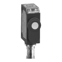
mic+ ultrasonic sensors are used for
non-contact detection of objects.
Synchronisation
If the assembly distances shown in
Fig. 1 for two or more sensors are ex-
ceeded the integrated synchronisation
should be used. Connect Sync/Com-
channels (pin 5 at the units receptable)
of all sensors (10 maximum).
mic+25... ≥0.35 m ≥2.50 m
mic+35... ≥0.40 m ≥2.50 m
mic+130... ≥1.10 m ≥8.00 m
mic+340... ≥2.00 m ≥18.00 m
mic+600... ≥4.00 m ≥30.00 m
Fig. 1: Assembly distances, indicating synchro-
nisation/multiplex
Multiplex mode
The Add-on-menu allows to assign an
individual address »01« to »10« to
each sensor connected via the Sync/
Com-channel (Pin5). The sensors per-
form the ultrasonic measurement se-
quentially from low to high address.
Therefore any influence between the
sensors is rejected.
The address »00« is reserved to syn-
chronisation mode and deactivates the
multiplex mode. To use synchronised
mode all sensors must be set to
address »00«.
Installation
Î
Assemble the sensor at the installa-
tion location.
Î
Plug in the connector cable to the
M12 connector, see Fig. 2.
1
5
2
colour
1 +U
B
brown
3 –U
B
blue
4 F black
2 – white
5 Sync/Com grey
Fig. 2: Pin assignment with view onto sensor
plug and colour coding of the microso-
nic connection cable
Start-up
Î
Connect the power supply.
Î
Set the parameters of the sensor
manually via TouchControl (see
Fig. 3 and Diagram 1)
Î
or use the Teach-in procedure to
adjust the detect points (see Dia-
gram 2).
T1 T2D1D2
3-digit
LED-display
Push-buttons T1 and T2
Measuring Range
LED D1 and D2
Fig. 3: TouchControl/LED display
Factory setting
mic+ sensors are delivered factory
made with the following settings:
Ԏ
Switching output on NOC
Ԏ
Detecting distance at operating ran-
ge
Ԏ
Measurement range set to maxi-
mum range
Maintenance
mic+ sensors work maintenance free.
Small amounts of dirt on the surface
do not influence function. Thick layers
of dirt and caked-on dirt affect sensor
function and therefore must be remo-
ved.
Notes
Ԏ
mic+ sensors have internal tempe-
rature compensation. Because the
sensors heat up on their own, the
temperature compensation reaches
its optimum working point after
approx. 30 minutes of operation.
Ԏ
During normal operating mode, a
yellow LED D2 signals that the swit-
ching output has connected.
Ԏ
During normal operating mode, the
measured distance value is dis-
played on the LED-indicator in mm
(up to 999 mm) or cm (from
100 cm). Scale switches automati-
cally and is indicated by a point on
top of the digits.
Ԏ
During Teach-in mode, the hystere-
sis loops are set back to factory set-
tings.
Ԏ
If no objects are placed within the
detection zone the LED-indicator
shows »– – –«.
Ԏ
If no push-buttons are pressed for
20 seconds during parameter set-
ting mode the made changes are
stored and the sensor returns to
normal operating mode.
Ԏ
The sensor can be reset to its facto-
ry setting, see »Key lock and facto-
ry setting«, Diagram 3.
Ԏ
The latest IODD file and informa-
tions about start-up and configura-
tion of pico+ sensors with IO-Link,
you will find online at
www.microsonic.de/en/mic+.
Show parameters
Î
In normal operating mode shortly
push T1. The LED display shows
»PAr.«
Each time you tap push-button T1 the
actual settings of the analogue output
are shown.
Diagram 1: Set sensor parameters numerically using LED display
T2
T1 + T2
T1 + T2
T1 + T2
T1 + T2
T1 + T2
T1 + T2
T1
T2
T1
T2
T1
T2
T1 T2
T2 T1
Start here
Press T1 and T2 simultaneously for about
3 s until welcome message has passed.
Set detect distance in
mm or cm.
For window mode
operation set far
switching point in
mm or cm.
For single switching
point press T2
until »
– – –« is
displayed.
Choose » « for NCC or
» « for NOC.
Ready
Set switching output
1
1 2
Operating Manual
mic+ Ultrasonic Sensors with
one switching output an IO-Link
mic+25/F/TC
mic+35/F/TC
mic+130/F/TC
mic+340/F/TC
mic+600/F/TC
SENSORPARTNERS.COM
Product description
Ԏ
The mic+ sensor with one switching
output measures the distance to an
object within the detection zone
contactless. Depending on the ad-
justed detect distance the switching
output is set.
Ԏ
All settings are done with two push-
buttons and a three-digit LED-dis-
play (TouchControl).
Ԏ
Three-colour LEDs indicate the swit-
ching status.
Ԏ
The output functions are changea-
ble from NOC to NCC.
Ԏ
The sensors are adjustable manually
via TouchControl or via Teach-in
procedure.
Ԏ
Useful additional functions are set
in the Add-on-menu.
Ԏ
Using the LinkControl adapter (op-
tional accessory) all TouchControl
and additional sensor parameter
settings can be adjusted by a Win-
dows
®
Software.
IO-Link
The mic+ sensors are IO-Link-capable
in accordance with IO-Link specifica-
tion V1.1 and support Smart Sensor
Profile like Digital Measuring Sensor.
The mic+ sensors have a blind zone
in which distance measurement is not
possible. The operating range indi-
cates the distance of the sensor that
can be applied with normal reflectors
with sufficient function reserve. When
using good reflectors, such as a calm
water surface, the sensor can also be
used up to its maximum range. Ob-
jects that strongly absorb (e.g. plastic
foam) or diffusely reflect sound (e.g.
pebble stones) can also reduce the
defined operating range.
Safety Notes
Ԏ
Read the operating instructions
prior to start-up.
Ԏ
Connection, installation and ad-
justment works may only be car-
ried out by expert personnel.
Ԏ
No safety component in ac-
cordance with the EU Machine
Directive, use in the area of per-
sonal and machine protection
not permitted
Proper Use
mic+ ultrasonic sensors are used for
non-contact detection of objects.
Synchronisation
If the assembly distances shown in
Fig. 1 for two or more sensors are ex-
ceeded the integrated synchronisation
should be used. Connect Sync/Com-
channels (pin 5 at the units receptable)
of all sensors (10 maximum).
mic+25... ≥0.35 m ≥2.50 m
mic+35... ≥0.40 m ≥2.50 m
mic+130... ≥1.10 m ≥8.00 m
mic+340... ≥2.00 m ≥18.00 m
mic+600... ≥4.00 m ≥30.00 m
Fig. 1: Assembly distances, indicating synchro-
nisation/multiplex
Multiplex mode
The Add-on-menu allows to assign an
individual address »01« to »10« to
each sensor connected via the Sync/
Com-channel (Pin5). The sensors per-
form the ultrasonic measurement se-
quentially from low to high address.
Therefore any influence between the
sensors is rejected.
The address »00« is reserved to syn-
chronisation mode and deactivates the
multiplex mode. To use synchronised
mode all sensors must be set to
address »00«.
Installation
Î
Assemble the sensor at the installa-
tion location.
Î
Plug in the connector cable to the
M12 connector, see Fig. 2.
1
5
2
colour
1 +U
B
brown
3 –U
B
blue
4 F black
2 – white
5 Sync/Com grey
Fig. 2: Pin assignment with view onto sensor
plug and colour coding of the microso-
nic connection cable
Start-up
Î
Connect the power supply.
Î
Set the parameters of the sensor
manually via TouchControl (see
Fig. 3 and Diagram 1)
Î
or use the Teach-in procedure to
adjust the detect points (see Dia-
gram 2).
T1 T2D1D2
3-digit
LED-display
Push-buttons T1 and T2
LED D1 and D2
Fig. 3: TouchControl/LED display
Factory setting
mic+ sensors are delivered factory
made with the following settings:
Ԏ
Switching output on NOC
Ԏ
Detecting distance at operating ran-
ge
Ԏ
Measurement range set to maxi-
mum range
Maintenance
mic+ sensors work maintenance free.
Small amounts of dirt on the surface
do not influence function. Thick layers
of dirt and caked-on dirt affect sensor
function and therefore must be remo-
ved.
Notes
Ԏ
mic+ sensors have internal tempe-
rature compensation. Because the
sensors heat up on their own, the
temperature compensation reaches
its optimum working point after
approx. 30 minutes of operation.
Ԏ
During normal operating mode, a
yellow LED D2 signals that the swit-
ching output has connected.
Ԏ
During normal operating mode, the
measured distance value is dis-
played on the LED-indicator in mm
(up to 999 mm) or cm (from
100 cm). Scale switches automati-
cally and is indicated by a point on
top of the digits.
Ԏ
During Teach-in mode, the hystere-
sis loops are set back to factory set-
tings.
Ԏ
If no objects are placed within the
detection zone the LED-indicator
shows »– – –«.
Ԏ
If no push-buttons are pressed for
20 seconds during parameter set-
ting mode the made changes are
stored and the sensor returns to
normal operating mode.
Ԏ
The sensor can be reset to its facto-
ry setting, see »Key lock and facto-
ry setting«, Diagram 3.
Ԏ
The latest IODD file and informa-
tions about start-up and configura-
tion of pico+ sensors with IO-Link,
you will find online at
www.microsonic.de/en/mic+.
Show parameters
Î
In normal operating mode shortly
push T1. The LED display shows
»PAr.«
Each time you tap push-button T1 the
actual settings of the analogue output
are shown.
Diagram 1: Set sensor parameters numerically using LED display
T2
T1 + T2
T1 + T2
T1 + T2
T1 + T2
T1 + T2
T1 + T2
T1
T2
T1
T2
T1
T2
T1 T2
T2 T1
Start here
Press T1 and T2 simultaneously for about
3 s until welcome message has passed.
Set detect distance in
mm or cm.
For window mode
operation set far
switching point in
mm or cm.
For single switching
point press T2
until »
– – –« is
displayed.
Choose » « for NCC or
» « for NOC.
Ready
Set switching output
1
1 2
Operating Manual
mic+ Ultrasonic Sensors with
one switching output an IO-Link
mic+25/F/TC
mic+35/F/TC
mic+130/F/TC
mic+340/F/TC
mic+600/F/TC
+32 (0)2 - 464 96 90
info@sensorpartners.com
sensorpartners.com
Z.1 Researchpark 310
B-1731, Zellik
Belgium
Sensor Partners BVBA
+31 (0)416 - 37 82 39
info@sensorpartners.com
sensorpartners.com
James Wattlaan 15
5151 DP Drunen
The Netherlands
Sensor Partners BV
Contact