SENSORPARTNERS.COM
2
4
5
3
U
+U
B
Sync/Com
1 Push-Pull output in pnp circuit
–U
B
F/
1
2
4
5
3
U
+U
B
Sync/Com
1 Push-Pull output in npn circuit
–U
B
F/
mic+25... mic+35...
mic+130...
mic+340... mic+600...
5
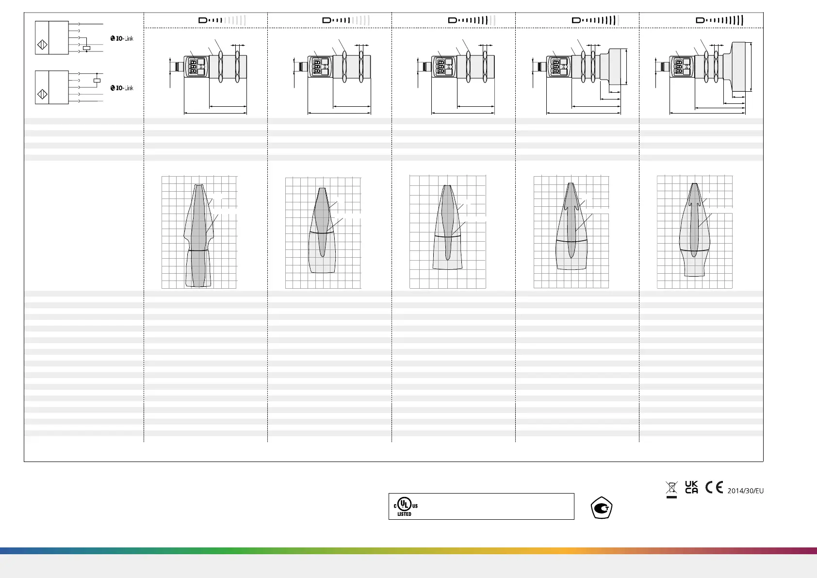
36 width A/F
LED-Display
2 Buttons
2 Duo-LEDs
84
51
M30x1.5
5
36 width A/F
LED-Display
2 Buttons
2 Duo-LEDs
84
51
M30x1.5
5
36 width A/F
LED-Display
2 Buttons
2 Duo-LEDs
84
51
M30x1.5
5
Ø47.5
36 width A/F
LED-Display
2 Buttons
2 Duo-LEDs
102
69
33
M30x1.5
19.5
5
36 width A/F
LED-Display
2 Buttons
2 Duo-LEDs
105
72
36
M30x1.5
22.5
Ø65
blind zone
0 to 30 mm 0 to 65 mm 0 to 200 mm 0 to 350 mm 0 to 600 mm
operating range
250 mm 350 mm 1,300 mm 3,400 mm 6,000 mm
maximum range
350 mm 600 mm 2,000 mm 5,000 mm 8,000 mm
angle of beam spread
see detection zone see detection zone see detection zone see detection zone see detection zone
transducer frequency
320 kHz 400 kHz 200 kHz 120 kHz 80 kHz
resolution
0.025 mm 0.025 mm 0.18 mm 0.18 mm 0.18 mm
detection zones
for different objects:
The dark grey areas represent the
zone where it is easy to recognise
the normal reflector (round bar).
This indicates the typical operating
range of the sensors. The light
grey areas represent the zone
where a very large reflector – for
instance a plate – can still be re-
cognised. The requirement here is
for an optimum alignment to the
sensor. It is not possible to evalua-
te ultrasonic reflections outside
this area.
Plate
0 cm
5 cm
10 cm
15 cm
20 cm
25 cm
30 cm
35 cm
10 cm
5 cm
0 cm
5 cm
10 cm
Round bar ø 10 mm
Plate
0 cm
10 cm
20 cm
30 cm
40 cm
50 cm
60 cm
20 cm
10 cm
0 cm
10 cm
20 cm
Plate
0 m
0.4 m
0.8 m
1.2 m
1.6 m
2 m
1.3 m
0.4
0 m
0.4
0.8
Round bar ø 27 mm
Plate
0 m
0.8
1.6
2.4
3.2
4 m
4.8
5.6
3.4
1.6
0.8
0 m
0.8
1.6
Round bar ø 27 mm
Plate
0 m
1.2
2.4
3.6
4.8
6 m
7.2
8.4
2.4
1.2
0 m
1.2
2.4
reproducibility ±0.15 % ±0.15 % ±0.15 % ±0.15 % ±0.15 %
accuracy ±1 % (Temperature drift internal compensated, may ±1 % (Temperature drift internal compensated, may ±1 % (Temperature drift internal compensated, may ±1 % (Temperature drift internal compensated, may ±1 % (Temperature drift internal compensated, may
be deactivated
3)
, 0.17%/K without compensation) be deactivated
3)
, 0.17%/K without compensation) be deactivated
3)
, 0.17%/K without compensation) be deactivated
3)
, 0.17%/K without compensation) be deactivated
3)
, 0.17%/K without compensation)
operating voltage U
B
9 to 30 V DC, short-circuit-proof, Class 2 9 to 30 V DC, short-circuit-proof, Class 2 9 to 30 V DC, short-circuit-proof, Class 2 9 to 30 V DC, short-circuit-proof, Class 2 9 to 30 V DC, short-circuit-proof, Class 2
voltage ripple ±10 % ±10 % ±10 % ±10 % ±10 %
no-load supply current ≤ 80 mA ≤ 80 mA ≤ 80 mA ≤ 80 mA ≤ 80 mA
housing Brass sleeve, nickel-plated, plastic parts: PBT, TPU; Brass sleeve, nickel-plated, plastic parts: PBT, TPU; Brass sleeve, nickel-plated, plastic parts: PBT, TPU; Brass sleeve, nickel-plated, plastic parts: PBT, TPU; Brass sleeve, nickel-plated, plastic parts: PBT, TPU;
Ultrasonic transducer: polyurethane foam, Ultrasonic transducer: polyurethane foam, Ultrasonic transducer: polyurethane foam, Ultrasonic transducer: polyurethane foam, Ultrasonic transducer: polyurethane foam,
epoxy resin with glass content epoxy resin with glass content epoxy resin with glass content epoxy resin with glass content epoxy resin with glass content
class of protection to EN 60529 IP 67 IP 67 IP 67 IP 67 IP 67
norm conformity EN 60947-5-2 EN 60947-5-2 EN 60947-5-2 EN 60947-5-2 EN 60947-5-2
type of connection 5-pin initiator plug, PBT 5-pin initiator plug, PBT 5-pin initiator plug, PBT 5-pin initiator plug, PBT 5-pin initiator plug, PBT
controls 2 push-buttons (TouchControl) 2 push-buttons (TouchControl) 2 push-buttons (TouchControl) 2 push-buttons (TouchControl) 2 push-buttons (TouchControl)
indicators 3-digit LED display, 2 three-colour LEDs 3-digit LED display, 2 three-colour LEDs 3-digit LED display, 2 three-colour LEDs 3-digit LED display, 2 three-colour LEDs 3-digit LED display, 2 three-colour LEDs
programmable with TouchControl and LinkControl with TouchControl and LinkControl with TouchControl and LinkControl with TouchControl and LinkControl with TouchControl and LinkControl
operating temperature –25 to +70 °C –25 to +70 °C –25 to +70 °C –25 to +70 °C –25 to +70 °C
storage temperature –40 to +85 °C –40 to +85 °C –40 to +85 °C –40 to +85 °C –40 to +85 °C
weight 150 g 150 g 150 g 210 g 270 g
switching hysteresis
1)
3 mm 5 mm 20 mm 50 mm 100 mm
switching frequency
2)
25 Hz 12 Hz 8 Hz 4 Hz 3 Hz
response time
2)
32 ms 64 ms 92 ms 172 ms 240 ms
time delay before availability <300 ms <300 ms <300 ms <380 ms <450 ms
order No. mic+25/F/TC mic+35/F/TC mic+130/F/TC mic+340/F/TC mic+600/F/TC
switching output Push-Pull, U
B
– 3 V, –U
B
+ 3 V, I
max
= 100 mA Push-Pull, U
B
– 3 V, –U
B
+ 3 V, I
max
= 100 mA Push-Pull, U
B
– 3 V, –U
B
+ 3 V, I
max
= 100 mA Push-Pull, U
B
– 3 V, –U
B
+ 3 V, I
max
= 100 mA Push-Pull, U
B
– 3 V, –U
B
+ 3 V, I
max
= 100 mA
switchable NOC/NCC, short-circuit-proof switchable NOC/NCC, short-circuit-proof switchable NOC/NCC, short-circuit-proof switchable NOC/NCC, short-circuit-proof switchable NOC/NCC, short-circuit-proof
1)
Can be programmed via TouchControl, LinkControl and IO-Link.
2)
With TouchControl, LinkControl and IO-Link, the selected filter setting and the maximum range influence the switching frequency and the response time.
3)
Can be deactivated via LinkControl.
microsonic GmbH / Phoenixseestraße 7 / 44263 Dortmund / Germany / T +49 231 975151-0 / F +49 231 975151-51 / E info@microsonic.de / W microsonic.de
The content of this document is subject to technical changes. Specifications in this document are presented in a descriptive way only. They do not warrant any product features.
no. 75330-19
Approved on
June 25th, 2019
Enclosure Type 1
For use only in industrial
machinery NFPA 79 applications.
The proximity switches shall be used with a
Listed (CYJV/7) cable/connector assembly ra-
ted minimum 32 Vdc, minimum 290 mA, in
the final installation.
*B13181*MV-DO-187552-761752
 Loading...