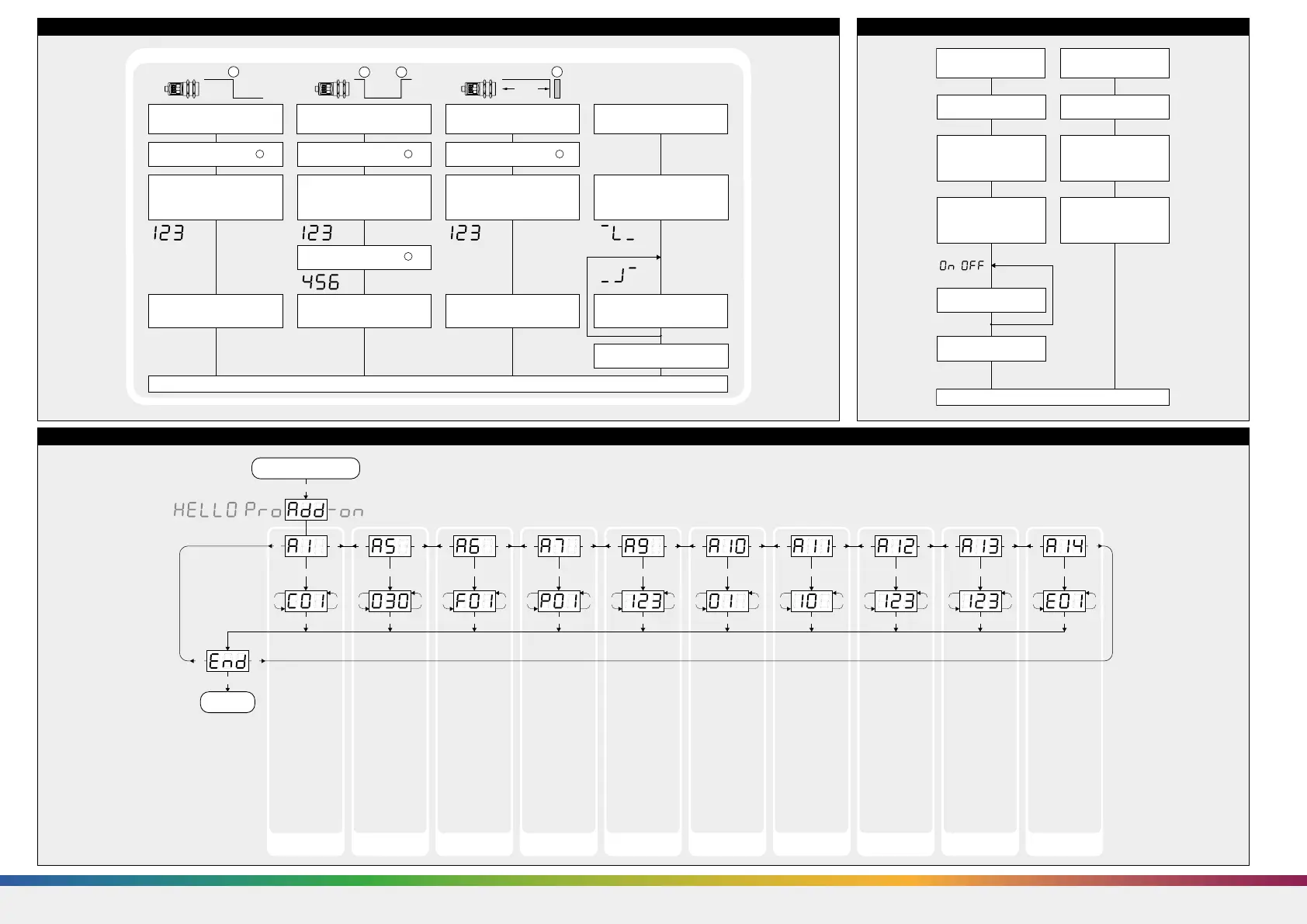
Diagram 4: Useful additional functions in Add-on menu (for experienced users only, settings not required for standard applications)
T2
T1 + T2
T1 + T2
T1 + T2T1 + T2 T1 + T2 T1 + T2 T1 + T2 T1 + T2 T1 + T2 T1 + T2 T1 + T2 T1 + T2
T1 + T2 T1 + T2 T1 + T2 T1 + T2 T1 + T2 T1 + T2 T1 + T2 T1 + T2 T1 + T2
T1 T2
T1T2
T1
T1 T1T2 T1T2 T1T2 T1T2 T1T2 T1T2 T1T2 T1T2 T2
T1 T2 T1 T2 T1 T2 T1 T2 T1 T2 T1 T2 T1 T2 T1 T2 T1 T2
T1 + T2
Start here
Ready
»C01«: Display
bright
»C02«: Display
dimmed
»C03«: Display off
Minimum value:
»001«
Maximum value:
difference between
maximum range and
switching point - 1
During window
mode operation
hysteresis influences
both switching
points.
»F00«: no filter
»F01«: standard
filter
»F02«: averaging
filter
»F03«: foreground
filter
»F04«: background
filter
Defines the strength
of the chosen filter.
»P00«: weak filter
up to
»P09«: strong filter
Minimum value:
blind zone
Maximum value: ne-
arwindow limit - 1
»00«: synchronisati-
on
»01« to »10«: sensor
address for multi-
plex mode
»oFF«: synchronisati-
on deactivated
To optimize multi-
plex speed the hig-
hest sensor address
may be set.
Setting range »01«
to »10«
Minimum value:
sensor-distant
window limit
Maximum value:
999 mm for
mic+25/...,
mic+35/...,
999 cm for
mic+130/...,
mic+340/...,
mic+600/...
Affects the size of
the detection zone.
»E01«: high
»E02«: standard
»E03«: slight
Put plane reflector
vertically disposed in
front of sensor: in
an exact distance of
250 mm for
mic+ 25... and
mic+35... and
900 mm for all other
types.
Adjust display to
250 mm or 900 mm.
Confirm calibration
with T1+T2.
Low power mode Hysteresis
switched output
Measurement filter Filter strength Foreground
suppression
Multiplex mode
device addressing
Multiplex mode
highest address
Measurement range Detection zone
sensitivity
Calibration
display
Diagram 2: Set sensor parameters via Teach-in procedure
Place object at position .
1
Set switching point
Press T1 and T2 simultaneously
until »End« is displayed.
Normal operating mode
Teach-in switching output
Press T2 until »d« is shown.
Press T2 until countdown passed
from »8 « to »0« and NOC or
NCC symbol is displayed.
Press T2 until »End« is shown.
To change output
characteristic press T2.
Current measuring
value
Place reflector at position .
1
Set two way reflective barrier Set NOC/NCC
Press T2 until »d« is shown.
Press T2 until countdown passed
from »8 « to »0« and »End«
is displayed.
Current measuring
value
Place object at position .
1
Place object at position .
2
Set window limits
Press T2 until »d« is shown.
Press T2 until »End« is shown.
Current measuring
value
Current measuring
value
NOC symbol
or NCC symbol
1
1 2
%85
1
Diagram 3: Key lock and factory setting
Activate/deactivate
TouchControl
Normal operating mode
Turn supply voltage OFF. Turn supply voltage OFF.
To activate or
deactivate press T1.
Don´t press any
push-button for 20 s.
While pressing T1 turn
supply voltage ON.
While pressing T1 turn
supply voltage ON.
Keep T1 pressed
until »on« or »off«
is displayed .
Reset to factory setting
Keep T1 pressed for about
15 s until »rESEt« has
passed through the display.
»on« or »off«
»off« or »on«
/
Note
Changes in the Add-on menu
may impair the sensor func-
tion.
A6, A7, A10, A11, A12 have
influence on the response
time of the sensor.
SENSORPARTNERS.COM
 Loading...