54 MDS 9810 Installation and Operation Guide MDS 05-3301A01, Rev. C
A complete explanation of remote diagnostics can be found in MDS’
Network-Wide Diagnostics System Handbook (MDS P/N
05-3467A01).
1. Program one radio in the network as the root radio by entering the
DTYPE ROOT command at the radio.
2. At the root radio, use the
DLINK ON and DLINK [baud rate] commands
to configure the diagnostic link protocol on the RJ-11 port.
3. Program all other radios in the network as nodes by entering the
DTYPE NODE command at each radio.
4. Use the
DLINK ON and DLINK [baud rate] commands to configure the
diagnostic link protocol on the RJ-11 port of each node radio.
5. Connect same-site radios using a null-modem cable at the radios’
diagnostic ports.
6. Connect a PC on which MDS Network Management Software is
installed to the root radio, or to one of the nodes, at the radio’s diag-
nostic port. (This PC may be the PC being used to collect payload
data, as shown in Figure 30.)
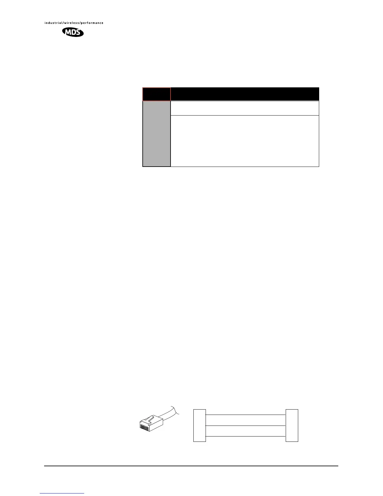
To connect a PC to the radio’s
DIAG. port, an RJ-11 to DB-9 adapter
(MDS P/N 03-3246A01) is required. If desired, an adapter cable
may be constructed from scratch, using the information shown in
Figure 27.
Invisible place holder
Figure 27. RJ-11 to DB-9 Adapter Cable
Table 13. Network-Wide Diagnostics Radio Setup Commands
COMMAND DESCRIPTION
NETWORK-WIDE
DIAGNOSTICS
CONFIGURATION
DLINK [xxxxx]
Details Page 55
Set baud rate of diagnostics link
DTYPE
[NODE/ROOT/GATE/PEER]
Details Page 55
Set radio’s operational characteristics
for network-wide diagnostics
RXD
TXD
GND
2
3
5
DB-9 FEMALE
(TO COMPUTER)
TXD
RXD
GND
4
5
6
RJ-11 PLUG
(TO RADIO)
RJ-11 PIN LAYOUT
1
6