C/O
oscillator
to talk
ON
LINK
talk ext talk int
talk mic
comms
+6
0
+6 +6
00
1
2
3
4
5
6
7
8
a
u
t
o
m
u
t
e
r
g
o
u
p
m
a
s
t
e
r
s
ext
int
talk talk
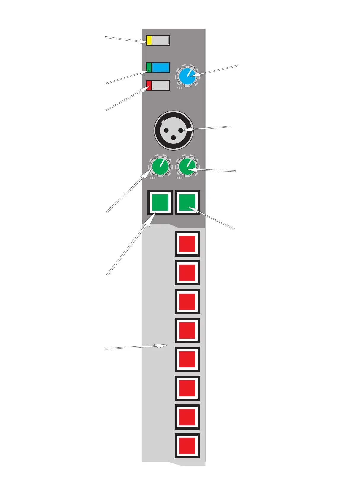
The OSCILLATOR TO TALK
CHANGE OVER switch
connects the oscillator and
pink noise signals to the talk
system in place of the talk mic.
The COMMS ON switch sends
the comms headset mic
amplifier signal to the comms
output / input connector.
The LINK switch connects the
talk mic to the intercom in
such a way that the talk mic,
headphones and PFL speaker
output can send and receive
(respectively) "clearcom"
signals as well as the headset.
When in LINK mode the
COMMS ON switch activates
the talk mic onto the comms
system with the side tone
cancel circuit preventing howl
round.
The COMMS control gives
continuous adjustment of the
incoming "clearcom" signals
that feed to the headset and has
a range from + 6dB to off.
The TALK XLR socket accepts
balanced 150 Ohm microphone
signals from - 50dBu to -
20dBu and uses an auto ranging
gain system to bring the signal
The TALK EXTERNAL
control gives continuous
adjustment of the talk mic
amplifier signals that will feed
the talk external output. The
adjustment range is from +
6dB to off.
The TALK EXTERNAL
switch connects the talk mic to
the talk external output and
dims the local monitor outputs
by 20dB to prevent howl
The TALK INTERNAL
control gives continuous
adjustment of the talk mic
amplifier signals that will feed
the internal talk system. The
adjustment range is from +
6dB to off.
The TALK INTERNAL switch
connects the talk mic to the
internal talk system and dims
the local monitor outputs by
20dB to prevent howl round.
None of the talk internal and
external controls act on signals
sent to the comms system when
in LINK mode.
The AUTO MUTE GROUP
MASTER switches (1 to 8)
activate the mute circuits on
any appropriately mute group
assigned input channel or
audio group.
35