EasyManua.ls Logo

Midco Economite RE4850A - User Manual

Default Icon
18 pages
Print Icon
To Next Page IconTo Next Page
Loading...
Installation and Service Instructions
Midco
®
International Inc.
4140 West Victoria Street
Chicago, Illinois 60646
toll free 866.705.0514
tel 773.604.8700
fax 866.580.8700
web www.midcointernational.com
e-mail sales@midcointernational.com
Quality Designed for Proven Performance
Printed in USA
8471 20
In the United States, Installation must conform with local codes or,
in the absence of local codes, with Installation of the National
Fuel Gas Code, ANSI Z223.1-latest edition, from the American
National Standard Institute. Further reference should be made
to the recommendation of your fuel supplier.
In Canada, Installation must conform with local codes or, in the
absence of local codes, with Installation Codes for Gas Burning
Appliances and Equipment, CGA Standard CAN/CGA 1B-149.
Further reference should be made to the recommendation of
your fuel supplier.
WARNING: Additions, changes, conversions,
and service must be performed by an authorized MIDCO
representative, service agency, or the fuel supplier. Use only
MIDCO speci ed and approved parts.
INSTALLER: Inform and demonstrate to the user the correct
operation and maintenance of the gas utilization equipment.
Inform the user of the hazards of storing ammable liquids
and vapors in the vicinity of this gas utilization equipment and
remove such hazards. A x this manual and associated
literature adjacent to the burner.
CODE COMPLIANCE IS THE SOLE
RESPONSIBILITY OF THE INSTALLER.
USER: Retain this manual for future reference. If other than
routine service or maintenance as described in this manual
and associated literature is required, contact a quali ed
service agency. DO NOT ATTEMPT REPAIRS. An inadvertent
service error could result in a dangerous condition.
!
WARNING: If the information in these instructions
is not followed exactly, a re or explosion may result,
causing property damage, personal injury or death.
Do not store or use gasoline or other ammable vapors and
liquids in the vicinity of this or any other appliance.
WHAT TO DO IF YOU SMELL GAS:
Do not try to light any appliance.
Do not touch any electrical switch; do not use any
phone in your building.
Immediately phone your gas supplier from another
building. Follow the gas supplier’s instructions. If
you cannot reach your gas supplier call the re
department.
Installation and service must be performed by a quali ed
installer, service agency or the gas supplier.
BURNER MODEL: ___________________________________
BILL OF MATERIAL
NUMBER: ___________________________________
SERIAL NUMBER #: ___________________________________
WIRING DIAGRAM: ___________________________________
FOR SERVICE CONTACT
Name: ____________________________________________
Address: ____________________________________________
____________________________________________
Phone: ____________________________________________
Date of Installation: ___________________________________
AVOID ERROR IN PARTS SELECTION. When ordering use complete MIDCO
Part Number and Description. Furnish Burner Model Number, Bill of Material
Number and Serial Number (if available) from the speci cation plate found on the
product.
IMPORTANT: Availability of parts as well as speci cations are subject to change
without notice. Please consult factory for item availability.
SAFETY INFORMATION TERMS: The following terms are used to identify hazards, safety precaution of special notations
and have standard meanings throughout this manual. They are printed in all capital letters using a bold type face as shown
below, and preceded by the exclamation mark symbol. When you see the safety alert symbol and one of the safety information
terms as shown below, be aware of the hazard potential.
DANGER: Identi es the most serious hazards which will result in severe personal injury or death.
WARNING: Signi es a hazard that could result in personal injury or death.
CAUTION: Identi es unsafe practices which would result in minor personal injury or
product and property damage.
!
!
822
Economite
RE4850A / RE4400
Gas Burners
US
C
LISTED
L
U
®
Question and Answer IconNeed help?

Do you have a question about the Midco Economite RE4850A and is the answer not in the manual?

Summary

General Information and Safety

Installation Codes and Compliance

Outlines installation requirements based on local and national codes.

Critical Safety Warnings

Highlights essential warnings regarding fire, explosion, gas hazards, and qualified service.

User and Installer Responsibilities

Defines duties for installers and users regarding operation, maintenance, and repairs.

Safety Information Terms

Explains hazard levels: DANGER, WARNING, CAUTION.

Part 1 Installation

Burner Specifications

Details model specs, firing rates, gas pressures, dimensions, electrical supply.

Ventilation Requirements

Specifies air infiltration needs for combustion and flue gases.

Equipment Preparation and Mounting

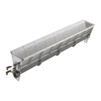
Covers cleaning, door access, safety valves, and combustion chamber setup.

Chimney, Venting, and Draft Control

Discusses requirements for chimneys, vent connectors, and draft regulation.

Electrical Wiring and Grounding

Covers wiring diagrams, grounding, polarity, and limit controls for safe operation.

Draft Hood Installation Recommendations

Illustrates recommended locations for draft hoods for proper venting.

Gas Supply Piping Requirements

Details gas line sizing, pressure limits, and installation of traps and regulators.

Gas Piping Diagrams

Illustrates piping configurations for RE4400 and RE4850A models.

Pipe Capacity and Leak Testing

Provides pipe sizing data and guidelines for leak testing gas lines.

Main Gas Input Selection

Discusses setting the gas input based on heating load and equipment capacity.

Initial Startup and Gas Settings

Covers initial checks, purging, and preliminary gas settings for startup.

Final Adjustments and Testing

Details final combustion adjustments, flue gas analysis, and completing the data tag.

Part 2 Service

Pilot System Service and Specifications

Describes the pilot system, specifications, and adjustment procedures.

Pilot Adjustment and Positioning

Covers fine-tuning pilot pressure, and correct positioning of spark and flame rods.

Motor Blower and Interlock Testing

Explains servicing the blower motor, air pressure switch, and testing the interlock circuit.

Gas Safety Valve Service

Details servicing and replacement of diaphragm and solenoid gas safety valves.

Valve Train and Sequence of Operations

Covers optional motorized valves, operational sequences, and primary safety control functions.

Primary Safety Control

Explains the function and use of the primary safety control module.

Special Equipment Considerations

Discusses variations due to factory or field-installed special equipment.

Part 3 Maintenance

General Maintenance Procedures

Covers keeping the area clear and motor bearing maintenance.

Consumer Lighting and Shut-Off Instructions

Provides step-by-step guidance for starting, stopping, and emergency shut-off.

Overview

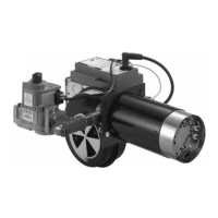
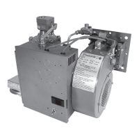
The Midco Economite RE4850A / RE4400 Gas Burners are designed for gas utilization equipment, including gravity and forced circulation furnaces and boilers. They are particularly suited for firing horizontal or downdraft equipment, as they do not require a draft to maintain a pilot. Their power burner design makes them ideal for replacing oil burners in rooftop and industrial applications.

Function Description:

These burners operate with an intermittent and interrupted spark-ignited pilot. The RE4850A and RE4400 models are designed to provide efficient combustion by mixing blower air with gas through a pilot orifice, creating a flame that ignites the main gas and is sensed by a flame rod. The system incorporates electronic flame safety with a 100% shut-off feature to ensure safe operation.

Important Technical Specifications:

  • Air Delivery (Approximate at Zero Draft): 125 SCFM (Standard Cubic Feet per Minute) for both RE4850A and RE4400.
  • Firing Rate (Natural or Propane):
    • RE4850A: Maximum 850 MBH (1,000 BTU/hr), Minimum 280 MBH.
    • RE4400: Maximum 400 MBH, Minimum 132 MBH.
    • All ratings are based on 1000 BTU/Cu. Ft. Natural gas. Derate burner for altitudes over 2,000 feet by 4% for each 1,000 feet above sea level.
  • Gas Supply Pressure Required:
    • Natural: 7.0" to 14.0" W.C. (Water Column).
    • Propane: 5.0" to 14.0" W.C.
  • Tube Diameter: 4".
  • Tube Length: 9".
  • Recommended Combustion Chamber Size (at Max. BTU/hr):
    • RE4850A: Width 15", Length 30".
    • RE4400: Width 10", Length 16.5".
  • Electrical Supply: 120 Volts / 60 Hertz.
  • Flame Safety: Electronic Flame Safety with Spark Ignited Pilot and 100% Shut-Off.
  • Pilot Gas Orifice Diameter: #54 Wire Drill (0.055") for both models, with an approximate capacity of 6000 BTU/Hr.
  • Pilot Gas Pressure:
    • Natural: 3.0" to 4.5" W.C.
    • Propane: 2.5" to 3.5" W.C.

Usage Features:

  • Installation: Must conform to local codes or, in their absence, to the National Fuel Gas Code (ANSI Z223.1) in the US, or Installation Codes for Gas Burning Appliances and Equipment (CGA Standard CAN/CGA 1B-149) in Canada.
  • Ventilation: Adequate air infiltration for combustion and dilution of flue gases is crucial. Specific requirements for open basements, utility areas, or tight rooms are provided, including sizing for permanently open grills based on BTU input.
  • Combustion Chamber Preparation: The combustion chamber, heat exchanger, and flue connections must be clean and free of tars, scale, dirt, and soot. Joints must be sealed to prevent leakage. A combustion chamber liner is typically required to protect non-heat transfer surfaces and provide a radiant bed. The burner tube or stainless steel sleeve must be sealed air-tight into the combustion chamber opening, positioned at least 1" short of the inside surface to prevent premature deterioration.
  • Mounting: Burners must be mounted in the orientations shown in Figures 1A and 1B to ensure safety and maintain warranty/approvals.
  • Chimney, Vent Connector, and Draft Control: The chimney must be inspected for unsafe conditions. The vent connector must be made of non-combustible, corrosion-resistant material, be as short as possible, readily accessible, and slope upward at least 1/4" per foot. A draft hood or barometric draft regulator must be installed, and a device to automatically shut off gas in case of sustained backdraft is required.
  • Electrical Wiring: Wiring and grounding must conform to local codes or, in their absence, to the National Electric Code (ANSI/NFPA No. 70) in the US, or Canadian Electrical Code Part 1 (CSA Standard C22.1) in Canada. Use 14-gage copper wire on a dedicated line with an on-off disconnect switch and a minimum 10 Amp breaker. The burner frame should be well grounded. Proper polarity (hot wire to L1, neutral to L2) is essential. Suitable limit controls are required, as existing oil burner controls are typically not suitable for gas burners.
  • Piping: Gas supply piping should branch off the main line near the gas meter. New black pipe and malleable fittings, free of defects, should be used. A sediment trap, union, and 1/8" pressure tap are required. Pipe joint compound approved for LP gases must be used. Gas supply piping must be sized to provide a minimum of 7.0" W.C. pressure at the upstream automatic safety shutoff valve when all gas utilization equipment is on. High pressure regulators must be adjustable to 14" W.C. outlet pressure.
  • Initial Startup/Adjustment:
    • Check for gas leaks with a soap solution.
    • Purge air from the gas supply line outside the building.
    • Set the burner input by adjusting the main gas pressure regulator according to Table 3 (Capacity and Preliminary Gas Settings).
    • Time the test dial for firing rate determination (Natural gas).
    • Check burner operation, limit controls, and flue gas temperature (325°F to 550°F).
    • Adjust combustion air shutter using an ORSAT or similar instrument to achieve approximately 9.5% CO2 for Natural gas or 12% for Propane.
    • Verify draft control to prevent spillage of flue products.
    • Fill out the Installation Adjustment Data Tag.
  • Pilot Operation: The pilot is a premix, blast type. Pilot operating pressures should be set as indicated in Table 4. The spark rod must be centered in the tee and held securely by the retaining bushing. The flame sensing rod must be positioned correctly for the Primary Safety Control to detect a proper flame.

Maintenance Features:

  • General Maintenance: Keep the area around the burner clear of combustible materials. Do not obstruct air openings or ventilation grills.
  • Motor Blower Interlock: The blower wheel should be cleaned if flame character indicates an air deficiency. Motor cooling air vents should also be cleaned. The motor and wheel are removed as an assembly. The burner is equipped with a diaphragm-type air pressure switch to prevent firing if the blower wheel is not running at operating speed.
  • Valve Train: Solenoid gas safety valves normally require no service. If leakage or malfunction occurs, the entire valve must be replaced. Motorized main automatic valves, if installed, should be checked for operation. The actuator assembly should not be disassembled; if it malfunctions, replace the entire assembly.
  • Primary Safety Control: This low-voltage, solid-state, direct spark ignition control module (e.g., Honeywell RM7895A or Siemens LME7) controls the gas valve, monitors the main burner flame, and generates high voltage for spark ignition. It uses separate electrodes for spark ignition and flame sensing and includes a 30-second minimum delay for system pre-purge. Refer to the manufacturer's literature for specific maintenance procedures.
  • Troubleshooting: A detailed trouble chart is provided for diagnosing issues such as the motor not running, motor running continuously with no pilot flame, or pilot lighting but no main flame. It emphasizes checking electrical components and flame-related issues in a specific order.
  • Safety Precautions:
    • Additions, changes, conversions, and service must be performed by an authorized MIDCO representative, service agency, or fuel supplier using only MIDCO specified and approved parts.
    • Do not store or use gasoline or other flammable vapors near the appliance.
    • If gas is smelled, do not light appliances, touch electrical switches, or use phones in the building. Immediately contact the gas supplier or fire department.
    • Do not tamper with the unit or controls.
    • Always close main and pilot manual shut-off valves and turn off burner power before servicing.
    • Cover plates, guards, and enclosures must be maintained in place except during maintenance.
    • Do not indiscriminately increase pilot orifice size.
    • Label all wires prior to disconnection when servicing controls to prevent wiring errors.
    • Do not use oxygen for pressure testing, as it poses an explosion hazard.
    • Disconnect low-pressure components during supply pipe leak testing to avoid damage from excessive pressure.
    • Do not use electronic devices if they get wet, as this can cause malfunction and serious injury.
    • Repeated unsuccessful attempts to light the burner can lead to accumulated gases and an explosive level; periodically purge the system as described in the startup procedure.

Midco Economite RE4850A Specifications

General IconGeneral
BrandMidco
ModelEconomite RE4850A
CategoryBurner
LanguageEnglish

Related product manuals