EasyManua.ls Logo

Midco J121-DS - User Manual

Midco J121-DS
12 pages
Print Icon
To Next Page IconTo Next Page
Loading...
Installation and Service Instructions
Midco
®
International Inc.
4140 West Victoria Street
Chicago, Illinois 60646
toll free 866.705.0514
tel 773.604.8700
fax 866.580.8700
web
www.midcointernational.com
e-mail sales@midcointernational.com
Quality Designed for Proven Performance
Printed in USA
8471 15
In the United States, installation must conform with local codes or
in the absence of local codes, with the National Fuel Gas Code,
ANSI Z223.1-latest edition available from American National
Standard Institute. Further reference should be made to the
recommendation of your fuel supplier.
In Canada, installation must conform with local codes or in the
absence of local codes, with Installation Codes for Gas Burning
Appliances and Equipment, CGA Standard CAN/CGA 1-B-149.1
or 2.
WARNING: Additions, changes, conversions
and service must be performed by an authorized Midco
representative, service agency or the fuel supplier. Use only
MIDCO specifi ed and approved parts.
INSTALLER: Inform and demonstrate to the user the correct
operation and maintenance of the gas utilization equipment.
Inform the user of the hazards of storing ammable liquids and
vapors in the vicinity of this gas utilization equipment and remove
such hazards. Affi x this manual and associated literature to the
burner.
CODE COMPLIANCE IS THE SOLE
RESPONSIBILITY OF THE INSTALLER.
USER: Retain this manual for future reference. If other than
routine service or maintenance as described in this manual
and associated literature is required, contact a qualifi ed service
agency. DO NOT ATTEMPT REPAIRS. An inadvertent service
error could result in a dangerous condition.
WARNING: If the information in these instructions
is not followed exactly, a fi re or explosion may result,
causing property damage, personal injury or death.
Do not store or use gasoline or other fl ammable vapors and
liquids in the vicinity of this or any other appliance.
WHAT TO DO IF YOU SMELL GAS:
Do not try to light any appliance.
Do not touch any electrical switch; do not use any
phone in your building.
Immediately phone your gas supplier from another
building. Follow the gas supplier’s instructions. If
you cannot reach your gas supplier call the fi re
department.
Installation and service must be performed by a qualifi ed
installer, service agency or the gas supplier.
SAFETY INFORMATION TERMS: The following terms are used to identify hazards, safety precaution of special notations and
have standard meanings throughout this manual. They are printed in all capital letters using a bold type face as shown below, and
preceded by the exclamation mark symbol. When you see the safety alert symbol and one of the safety information terms as shown
below, be aware of the hazard potential.
DANGER: Identifi es the most serious hazards which will result in severe personal injury or death.
WARNING: Signifi es a hazard that could result in personal injury or death.
CAUTION: Identifi es unsafe practices which would result in minor personal injury or product and property
damage.
BURNER MODEL: ___________________________________
BILL OF MATERIAL
NUMBER: ___________________________________
SERIAL NUMBER #: ___________________________________
WIRING DIAGRAM: ___________________________________
FOR SERVICE CONTACT
Name: ____________________________________________
Address: ____________________________________________
____________________________________________
Phone: ____________________________________________
Date of Installation: ___________________________________
Incinomite
Model J121-DS
Gas Burner
C
O
M
P
A
N
Y
R
E
G
I
S
T
E
R
E
D
AVOID ERROR IN PARTS SELECTION. When ordering use complete MIDCO
Part Number and Description. Furnish Burner Model Number, Bill of Material
Number and Serial Number (if available) from the specifi cation plate found on the
product.
IMPORTANT: Availability of parts as well as specifi cations are subject to change
without notice. Please consult factory for item availability.
MADE in the USA
As an ISO 9001:2008 certi ed company, we proudly design, manufacture and assemble our products in Chicago, Illinois, USA.
The INCINOMITE Model J121-DS gas burner features direct main
ame spark ignition and solid state electronic fl ame verifi cation.
917
Question and Answer IconNeed help?

Do you have a question about the Midco J121-DS and is the answer not in the manual?

Summary

Specifications

Burner Air Delivery and Firing Rates

Specifications for burner air delivery and firing rates for natural and propane gas.

Gas Pressure and Electrical Requirements

Details on minimum gas pressure, electrical supply, and control systems.

Flame Safety and Firing Angle

Information on flame safety features and the adjustable firing angle.

Part 1 Installation

Primary Chamber Fuel Input

Guidance on fuel input for primary chamber based on waste type.

Indoor Ventilation Requirements

Critical ventilation needs for the incinerator room and burner operation.

Installation Details

Specific instructions for installing the burner within the incinerator.

Chimney, Vent Connector, and Draft Control

Chimney and Venting Requirements

Conformance to codes for chimney, vent connector, and draft control components.

Part 1 Installation

Piping Requirements

Guidelines for gas piping installation, including materials and pressure considerations.

Electrical Installation

Wiring and Grounding

Instructions for wiring the burner, including code compliance and grounding.

Initial Start Up and Adjustment

Startup Procedures

Procedures for initial startup, ignition, and adjusting burner operation.

Startup and Adjustment Details

Further details and diagrams for burner startup and adjustment procedures.

Startup, Adjustment and Diagrams

Continued guidance on startup, adjustment, and control component diagrams.

Part 2 Service

Ignitor and Regulator Assembly

Guidance on servicing the ignitor and regulator assembly, including common issues.

Ignitor Gas;Air Adjustment

Instructions for adjusting the ignitor gas and air mixture for optimal performance.

Main Automatic Valve

Information on the main automatic gas valve and its function.

Blower Assembly Service

Maintenance and cleaning procedures for the blower assembly.

Thermal Switch Function

Explanation of the thermal switch operation and testing procedure.

Electronic Control System

Control System Overview

Description of the solid state electronic control for ignition and flame monitoring.

Ignitor and Flame Sensor Assembly

Details and diagrams for the ignitor and flame sensor assembly.

Trouble Shooting

Electrical and Flame Checks

Systematic checks for electrical and flame-related issues in order.

Motor Operation Issues

Troubleshooting steps for motor not running or running continuously.

Ignition and Flame Problems

Diagnosing issues with ignition spark, gas pressure, and flame.

Trouble Shooting

Flame During Ignition Trial

Troubleshooting when flame is only present during the 6-second trial for ignition.

Flame Characteristics

Diagnosing issues related to short or long, hazy flame characteristics.

Gas Shut Off Failure

Troubleshooting when the gas fails to shut off properly.

Overview

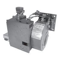
The Incinomite Model J121-DS Gas Burner is a robust and efficient heating device designed for various applications, particularly in incinerators. It features direct main flame spark ignition and solid-state electronic flame verification, ensuring reliable and safe operation.

Function Description:

The burner automatically ignites and monitors the flame using a 24-volt AC solid-state electronic control system. This system includes an integral high-voltage transformer. Upon flame startup, high voltage is applied to the spark electrode and 24V to the Main Automatic Gas Valve. Once the flame is proven, the spark is terminated, and the burner continues to run. If the flame is not proven within 6 seconds, or if the flame is lost during operation and not re-established within 6 seconds, the control will shut off the Main Automatic Gas Valve and lock out. To reset, the Burner Switch or Timer must be turned off for at least 30 seconds and then turned back on.

Important Technical Specifications:

  • Burner Air Delivery: Approximately 180 SCFM (Standard Cubic Feet/Minute) at zero draft.
  • Minimum Gas Pressure for Input Adjustment (at Inlet Tap of Main Automatic Valve):
    • Natural Gas: 5.5" W.C.
    • Propane Gas: 8.0" W.C.
  • Burner Firing Rate (Natural or Propane):
    • Minimum: 100 MBH (100,000 BTU/Hr.)
    • Maximum (With Combustion Air From Burner Only):
      • 20% Excess Air: 900 MBH
      • 0% Excess Air (stoichiometric): 1080 MBH
    • Maximum (With Combustion Air From Burner Blower and Additional Air Available in Combustion Chamber):
      • Natural Gas (5.5" W.C.) or Propane Gas (11.0" W.C.) Gas Pressure at Main Automatic Valve: 1,200 MBH
  • Electrical Supply: 120/1/60; 4.5 amps
  • Burner On-Off Control: Toggle Switch
  • Flame Safety: Electronic Flame Safety with spark ignited ignitor (pilot) and 100% shut-off.
  • Adjustable Firing Angle: Adjustable for horizontal or 10° down firing.
  • Ignitor Orifice Diameter:
    • Natural Gas: .070 (#50 DR)
    • Propane Gas: .063 (#52 DR)
  • Recommended Ignitor Gas Pressure: 3.5" W.C. for both Natural and Propane gas.
  • Ignitor Gas Rate: 13 MBH for Natural Gas, 15 MBH for Propane Gas.
  • Motor: 1/6 HP split phase 3450 RPM motor, with either a manual or auto-reset overload protector.

Usage Features:

  • Fuel Compatibility: Suitable for use with NATURAL or PROPANE gas only. Conversion kits are available for field conversion to PROPANE gas.
  • Installation: Burners should be installed level with the top of the highest normal load and fire with or across the draft flow. The blast tube should not protrude into the incineration chamber. The mounting flange can be rotated 180° for horizontal or 10° down firing.
  • Piping: Supply piping must conform to local and national codes, using new black pipe and malleable fittings. A suitable Main Gas Pressure Regulator is required to adjust gas pressure to the specified range. It is crucial that regulated gas pressures do not exceed 14" W.C. to prevent damage.
  • Electrical Wiring: Installation wiring must conform to local codes (ANSI/NFPA No. 70 in the US, CSA standard C22.1 in Canada). Copper wires and disconnect/fuse protection are required. The burner frame must be well grounded.
  • Initial Start-Up/Adjustment:
    • Check for gas leaks with a weak liquid soap solution.
    • Confirm Main Gas Input Adjuster is 5 to 6 turns from full closed and Blower Air Shutter is fully open.
    • Purge air from the gas supply line outside the building.
    • Observe ignitor flame and adjust the Ignitor regulator for a stable blue flame (2 or more microamps).
    • Adjust the Main Gas Input Adjusting Screw to achieve the desired input rating.
    • Reset the Blower Air Shutter to match the intended input.
    • The ignitor gas/air mixture can be adjusted via a screw under a plug button in the Ignitor Block.
  • Safety: The burner is equipped with electronic flame safety and 100% shut-off. Warnings are provided against using oxygen for pressure testing, repeated unsuccessful light attempts leading to gas accumulation, and using a wet device due to explosion hazard.

Maintenance Features:

  • Ignitor and Regulator Assembly: Removed as a unit for servicing. Common issues include lint, dust, corrosion, cracked electrode insulators, or foreign matter in the blast tube.
  • Flame Sensor Rod: Proper operation can be checked by measuring flame current (should be steady 2 or more microamps).
  • Cleaning: Clean Ignitor Retention Plate ports, internal air and gas passages, Electrode Insulators, electrode ends, and Ground Barrier. Ensure no debris in the Blast Tube.
  • Ignitor Gas Orifice: Check and clean the ignitor gas orifice in the Tee Orifice Fitting.
  • Electrode Adjustment: Ensure electrode ends are positioned correctly and the gap between the electrode and ground barrier is spaced as per Figure 5.
  • Ignitor Air Deflector: Check the angle (45°).
  • Electrode Wire Insulation: Inspect for cracks, worn areas, or contact with the burner frame.
  • Main Automatic Valve: A single-function on-off type valve that closes automatically on current failure. Replace if it fails to open or leaks.
  • Blower Assembly: The motor features permanently lubricated ball bearings, requiring no routine oiling.
  • Blower Wheel: Cleaning is usually the only service required, especially if the inlet screen or blower wheel shows accumulation of dust and lint. Motor air cooling vents should also be cleaned.
  • Thermal Switch: A heat-sensitive single-pole double-throw snap switch that energizes the blower motor for cooling air if the blower housing temperature reaches 160° F. It is not wired into the gas valve circuit. The switch can be tested for continuity when cool (terminals 1 and 3) and when heated (terminals 1 and 2).

Midco J121-DS Specifications

General IconGeneral
BrandMidco
ModelJ121-DS
CategoryBurner
LanguageEnglish

Related product manuals