2
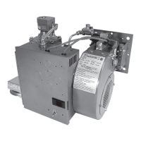
Midco International Inc.
8471 15
MADE in the USA
Specifi cations & Part 1 Installation
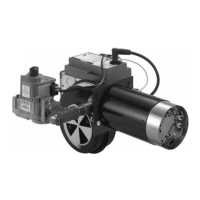
BURNER AIR DELIVERY
Approximate Air Delivery at Zero Draft ......................... 180 SCFM
2
MINIMUM GAS PRESSURE LISTED FOR PURPOSE OF
INPUT ADJUSTMENT
(Take Pressure at Inlet Tap of Main Automatic Valve)
NATURAL .................................................................... 5.5″ W.C.
PROPANE .................................................................... 8.0″ W.C.
BURNER FIRING RATE (NATURAL OR PROPANE)
3
MINIMUM .................................................................... 100 MBH
4
MAXIMUM (With Combustion Air From Burner Only).
20% Excess Air ..................................................... 900 MBH
0% Excess Air (stoichiometric) ................................ 1080 MBH
MAXIMUM (
With Combustion Air From Burner Blower
and Additional Air Available in Combustion Chamber.)
NATURAL Gas 5.5″ W.C. or PROPANE Gas at 11.0″ W.C.
Gas Pressure at Main Automatic Valve ......................... 1,200 MBH
ELECTRICAL SUPPLY ..................................................... 120/1/60;4.5 amps
BURNER ON-OFF CONTROL .............................................. Toggle Switch.
FLAME SAFETY .................................................................... Electronic Flame Safety
with spark ignited ignitor (pilot) and 100% shut-off .
ADJUSTABLE FIRING ANGLE .................................... Mounting Flange
adjustable for horizontal or 10° down fi ring.
NOTE: Burner components are UL recognized, CGA listed, CSA certifi ed and/or AGA design
certifi ed, mounted and wired. The complete burner is fi re tested.
1.
Standard burners are shipped as NATURAL gas models. A kit is available for fi eld conversion to
PROPANE gas.
2.
SCFM = Standard Cubic Feet/Minute.
3.
NOTE: Firing rate with combustion air from burner blower only is based on using standard air at sea
level with zero draft over-fi re. De-rate burner for altitudes over 2,000 feet by 4% for each 1000 feet of
additional elevation.
4.
100 MBH = 100,000 BTU/Hr.
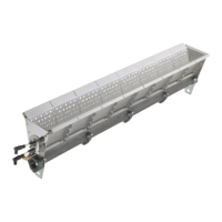
- No. 1 Waste: Primarily dry material such as paper, rags and wood. Burner normally required only
for light-off .
- No. 2 Waste: Consisting of approximately equal portions, by weight of No. 1 and No. 3 waste; 70
lbs. per 100 MBH.
- No. 3 Waste: Wet material such as garbage; 25 lbs. per 100 MBH.
- No. 4 Waste: Organic materials such as small carcasses and waste from hospital operating rooms
or pathological laboratories; 13 lbs. per 100 MBH.
NOTE: The burner input required for the secondary chamber must be determined from the heat
required to maintain the discharge temperature of the fl ue products as specifi ed by the EPA for the
type of waste involved and the location of the incinerator.
__________________________________________
Make sure that the incinerator room has suffi cient ventilation to provide the necessary combustion air
for the burner fuel, the waste material and any other appliance that would draw its air from the same
enclosed area.
WARNING: Under no condition should the access to outside air be so restricted that
the maximum possible use of combustion air is inhibited. Pay particular attention to exhaust
fans that could draw air from the area and create a negative pressure in the room
__________________________________________
Specifi cations
1
Part 1
Installation
I Primary Chamber
Fuel Input
II Indoor Ventilation