Midco International Inc.
9
8471 15
MADE in the USA
Part 2 Service
- Connect the high voltage wire to the spark electrode. Spark should be visible during 6-second trial for
ignition period and arc from the electrode end to the Ground Barrier. It should be audible and visible,
though it is rather thin and diffi cult to see in bright light.
CAUTION: Circuit has 30,000 volt open circuit potential.
- If the spark is not audible or visible it is leaking directly to ground. Before removing electrodes, check
to make sure voltage is available by positioning the spark wire 1/8″ from the end of the electrode.
- Disconnect Flame Electrode wire and switch the high voltage wire to the fl ame electrode and
repeat test for insulator leakage.
CAUTION: Do not indiscriminately change the ignitor gas orifi ce size as ignition
troubles are rarely cured in this manner. The ignitor utilizes a premixed gas/air mixture and, as
the air input is relatively fi xed, any adjustment to the gas/air ratio that might be required for a
specifi c application should be made by careful adjustment of the ignitor regulator to vary its
outlet gas pressure. Pressure adjustments must be made when the gas is fl owing. If cleaning
and electrode adjustment does not eliminate an ignition problem, further checks are required.
Refer to Trouble Chart.
__________________________________________
The ignitor assembly as shipped is pre-set during factory fi re-testing and normally needs no adjustment
except in installations where the air shutter is full open. The ignitor should not be adjusted until it is
confi rmed that good light-off s are not possible with ignitor gas pressure adjustments only as described
in Section VIII.
- The Air adjustment screw is located under a plug button in the Ignitor Block about 1/2″ behind the
Ignitor Orifi ce (refer to Figure 5). A 5/64 (.078) inch hexagon wrench is required for adjustment. Pry up
the plug button to expose air adjustment screw. Adjust the screw up or down to fi nd the best Flame
Signal or until repeatable and stable light-off s are achieved. Ignitor airfl ow is decreased as the screw
is turned clockwise, and increased as it is turned counter-clockwise. Generally 3 to 5 turns up from full
closed (screw bottomed out) works best.
- When adjustments are completed, replace plug button to protect adjustment screw.
__________________________________________
The valve is a single function on-off type with automatic closing on current failure. Replace entire valve
if valve fails to open when power is applied or if leakage is defected on standby.
__________________________________________
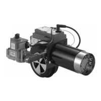
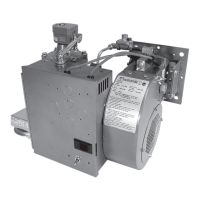
Model J121-DS is equipped with 1/6 HP split phase 3450 RPM motor. It may contain either a manual
or auto-reset overload protector. It has no interlock, this function being performed by an Air Pressure
Switch on the burner. The motor features permanently lubricated ball bearings that require no routine
oiling maintenance.
- Cleaning of the blower wheel is usually the only service required. Need for cleaning is required if
the inlet screen or blower wheel shows an accumulation of dust and lint. The motor air cooling vents
should also be cleaned at this time.
- If the motor must be replaced, disconnect the motor wires from the burner terminal strip. Remove the
blower inlet screen and blower wheel and remove the motor case bolt nuts and lock washers.
- When remounting the blower wheel, the distance from the wheel and the outside of the blower
housing air inlet side plate should be 5/16″.
__________________________________________
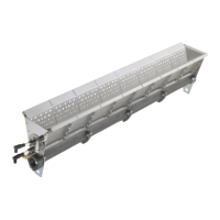
The Thermal Switch is a heat sensitive single pole double throw snap switch that energizes the blower
motor to provide cooling air if, because of a heat back up through the burner when the motor is off , the
temperature of the blower housing reaches 160° F. The thermal switch is not wired into the gas valve
circuit and does not turn valve off when activated by heat back up.
- The switch mechanism is a bi-metallic disc that snaps over when it is heated to the set temperature.
The switch is mounted so that the disc bears against the side plate of the blower housing.
- Testing the switch to prove that it is functional can be done by removing the ignitor assembly and
blowing hot air through the opening toward the blower inlet. If hot air is not available, remove the switch
and check for continuity. With the switch cool, there should be continuity between terminals 1 (black
wire) and 3
(red/black wire). To simulate the “hot” condition, place the switch on a fi rm surface and
apply fi nger pressure to the switch disc. When the disc “snaps”, there should be continuity between
terminals 1 and 2 (red wire).
__________________________________________
IX Ignitor Gas/Air
Adjustment
X Main Automatic
Valve
XI Blower Assembly
XII Thermal Switch
VIII Ignitor and
Regulator Assembly
Continued
 Loading...