8
Midco International Inc.
8471 15
MADE in the USA
Part 2 Service
_________________________________________
WARNING: BE SURE THAT THE MANUAL VALVE AND BURNER DISCONNECT SWITCH
ARE TURNED OFF BEFORE ANY PARTS ARE REMOVED FOR SERVICE.
The Ignitor and Regulator Assembly is removed as a unit. Disconnect the ignitor gas line and electrode
wires, remove the two mounting screws and pull out the assembly.
- When the ignitor gas pressure is in the proper range (see Table 3) and the electrodes are adjusted
to the dimensions shown in Figure 5, any ignition problems are usually caused by lint, dust, corrosion,
cracked electrode insulators, foreign matter in the blast tube or deterioration of ignitor ports in
Retention Plate.
- Ignitor trouble will be evidenced by failure of main burner ignition. It may cause frequent Electronic
Control lockout. Check for dirt in the ignitor air and mixture passageways and check for obstructions in
the ignitor ports. Also check electrode adjustments (see Figure 5). Replace any severely burned parts.
- Proper operation of the fl ame sensor rod can be checked by measuring the fl ame current. With the
Electronic Control energized, a good reading should run steady 2 or more microamps.
- When servicing, clean the Ignitor Retention Plate ports and blow out the internal air and gas passages.
Clean the Electrode Insulators and check them for hairline cracks. Also check the electrode ends and
the Ground Barrier for serious corrosion or loss of metal. Replace any defective parts.
- Make sure that there is no debris in the Blast Tube that could short out the Spark or Flame Electrode.
- Clean the Ignitor Gas Orifi ce in Tee Orifi ce Fitting (see Figure 5) and check that the orifi ce size is
correct per Table 3.
- Check that the electrode ends are positioned and that the gap between the end of each electrode
and the ground barrier is spaced per Figure 5.
- Check that the Ignitor Air Defl ector is at the correct angle (45°). See Figure 4.
- Inspect the electrode wire insulation for cracks or worn areas, or any contact with the burner frame.
Dampness will facilitate electrical leakage to ground, which will cause ignition or fl ame signal failure.
TYPE OF IGNITOR RECOMMENDED IGNITOR IGNITOR
GAS ORIFICE DIA. GAS PRESSURE GAS RATE
Natural . 070 ( #50 DR ) 3.5″ W.C. 13 MBH
Propane . 063 ( #52 DR ) 3.5″ W.C. 15 MBH
SPARK TEST—Main Manual Shut-Off Valve must be off . Place the Ignitor Assembly on top of the
burner with the electrode ends visible and good metal to metal contact between the Ignitor Mounting
Plate and the burner chassis.
VIII Ignitor and
Regulator Assembly
Table 3 Ignitor Firing Rate
100 200 300 400 500 600 700 800 900 1000 1100 1200
14
12
11
10
9
8
7
6
5
4
3
2
1
13
0
8.0
10.0
9.0
11.0
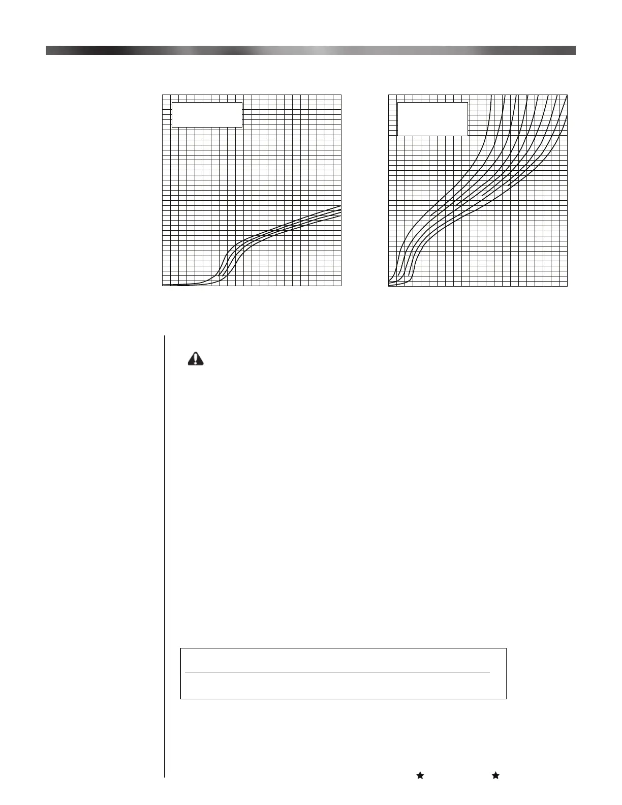
Input in MBH
Input Adjuster Setting in Numbers of Turns from Full Closed
15
19
16
17
18
100 200 300 400 500 600 700 800 900 1000 1100 1200
14
12
11
10
9
8
7
6
5
4
3
2
1
13
0
6.
Input in MBH
Input Adjuster Setting in Numbers of Turns from Full Closed
15
19
16
17
18
2.0 2.5 3.0 3.5 4.0 4.5 5.0 5.5
Propane Gas
2,500 BTU/Cu. Ft.
(with 5/8” Main Gas Port)
Natural Gas
1,000 BTU/Cu. Ft.
(with 5/8” Main Gas Tube
only, No Gas Port)
Gas Pressure at Main automatic Valve (Inches Water Column)
Table 2 Firing Rate Curves
VII Initial Start
Up/Adjustment
Continued
 Loading...