Do you have a question about the Midea ATOM B Series and is the answer not in the manual?
Details indoor and outdoor unit capacity ranges and model names for Atom series.
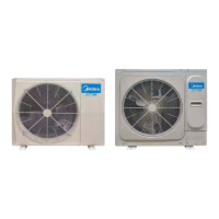
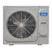
Visuals and descriptions of indoor and outdoor unit appearances.
Guidelines for combining indoor and outdoor units based on capacity ratios.
Schematics showing the piping layout for different model capacities.
Illustrates refrigerant flow during cooling, heating, and defrosting operations.
Overview of system control logic and operational states.
Details the conditions and reasons for system shutdown.
Describes the process and component actions during system startup.
Explains component control during standard cooling and heating modes.
Covers safety mechanisms and error codes for system protection.
Details specific operational modes like oil return and defrosting.
Configuration options and switch settings for outdoor units.
Identification of components within the outdoor unit's electric control box.
Details the main PCB layout and port functions for outdoor units.
Schematic diagrams illustrating electrical connections for different models.
Lists error codes, their content, and applicable models.
Provides procedures for diagnosing and resolving system faults and errors.
| Brand | Midea |
|---|---|
| Model | ATOM B Series |
| Category | Air Conditioner |
| Language | English |