Do you have a question about the Midea EL-KFR90GW/Y-A(B) and is the answer not in the manual?
| Brand | Midea |
|---|---|
| Model | EL-KFR90GW/Y-A(B) |
| Category | Air Conditioner |
| Language | English |
Guidelines for safe servicing procedures and precautions to prevent hazards.
Procedure for testing insulation resistance to prevent electrical hazards.
Overview of the air conditioner's key functionalities and capabilities.
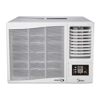
Details on the location and function of controls on the unit and remote.
Detailed dimensions and size classifications for various indoor unit models.
Diagrams and specifications for the installation plate and mounting clearances.
Detailed dimensions and size classifications for various outdoor unit models.
List of essential tools required for the proper installation of the air conditioner unit.
List of accessories and materials needed for unit installation.
Detailed steps for installing both the indoor and outdoor components of the air conditioner.
Specifications for piping length, elevation, and related considerations.
Instructions for fitting and securing the installation plate to the wall.
Guidance on drilling holes for piping and conduit through the wall.
Detailed procedure for performing correct flaring work on refrigerant pipes.
Steps to remove burrs from cut pipe sections to ensure proper sealing.
Instructions for correctly placing flare nuts onto the pipes before flaring.
Steps for connecting refrigerant pipes and drain hose to the indoor unit.
Procedure for routing piping and cables for rear right installation of the indoor unit.
Procedure for routing piping and cables for rear left installation of the indoor unit.
Steps for connecting refrigerant pipes to the outdoor unit.
Ensure all electrical work complies with relevant standards and electrical safety rules.
Important notes regarding power source, circuit breakers, and earthing requirements.
Connecting the electrical cable to the indoor unit's terminals.
Connecting the electrical cable to the outdoor unit's control board and terminals.
Procedures to check the indoor unit's drainage system for proper water flow.
Guidelines for correct drain hose orientation and avoiding issues like water blockage.
Instructions for insulating and securing the refrigerant piping.
Procedures for forming piping based on outdoor unit installation position relative to indoor unit.
Explanation of why air purging is necessary and its effects on system performance.
Detailed steps for evacuating the system using a vacuum pump and nitrogen.
Method for checking refrigerant joints and valves for leaks using soap water.
Procedure for evacuating the tubing and indoor unit using a vacuum pump.
Final steps for completing the air purging process and preparing for test run.
Proper anchoring and securing of the outdoor unit to prevent vibration and movement.
Instructions for installing batteries and preparing the remote control for operation.
Steps to run the unit using the indoor unit's manual control switch.
Checking system performance, refrigerant charge, and air intake/discharge temperatures.
Procedure for collecting refrigerant in the outdoor unit for servicing or relocation.
Schematic diagrams illustrating the refrigeration cycle for reverse cycle and cooling-only models.
Classification of common troubles, voltage limits, and temperature operation limits.
Tables mapping LED error indications to failure phenomena for troubleshooting.
A decision tree diagram to diagnose and resolve unit operating problems.
Causes and remedies for abnormal noises originating from indoor and outdoor units.
Common causes and solutions for poor cooling or heating performance.
Troubleshooting steps for water leakage issues from the indoor unit.
Diagnosis and correction for zero-crossing errors, potentially related to wiring or EMC.
Further causes and remedies for inadequate cooling or heating output.
Electrical schematics detailing wiring connections for various indoor unit models.
Specific wiring diagrams tailored to different outdoor unit model series.