3
PART FIGURE
NO. Description NO. Description
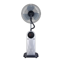
1 Spray cap
2 Corrugated hose
10 Motor assy
3 Front guard
11 Tightening knob
4 Screw (ST3*7.5)
12 Host assy
5 Net clamp
13 Base assy
6 Blade nut
14
Caster (Universal wheel)
7 Blade
15 Screw (M5*20)
Spring clamp
Drain plug
8 Guard nut
16
17
18
9 Rear guard
Water tank assy
All the pictures in this manual are for explanation purpose only. Any discrepan-
cy between the real object and the illustration in the drawing shall be subject to
the real subject.
Note:
pilot hole
INSTALLATION METHOD
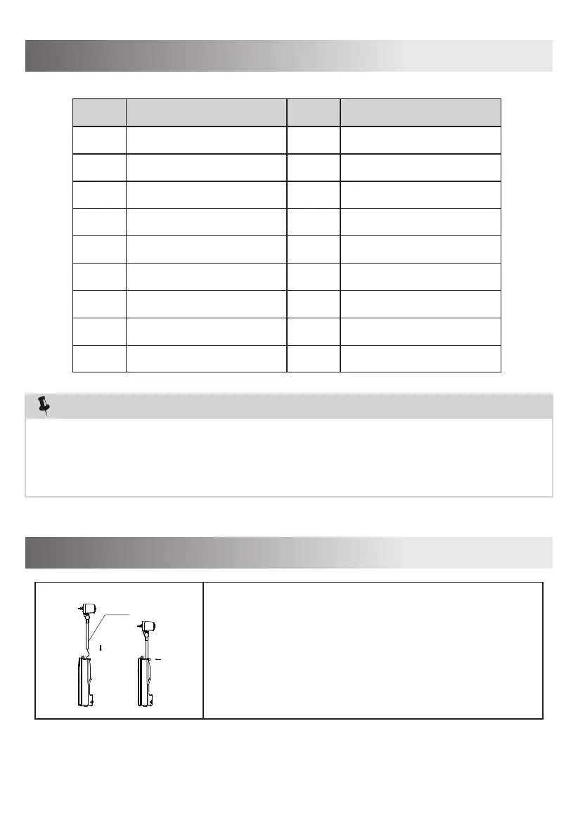
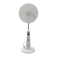
1. Assembly of host
Take out the motor assy and host assy from the
package,as is shown in Figure 1,insert the
connecting wire and the column into the host,then
tighten the fastening knob and ensure to drive the
screw into the positioning hole.
Fig.1