M thermal Split
Part 2 - Component Layout and
2 Piping Diagrams
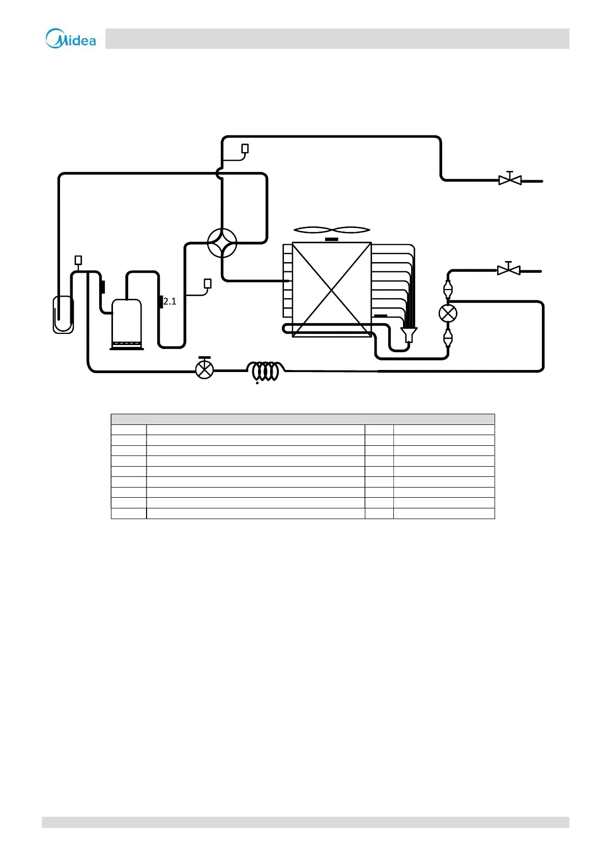
2.1 Outdoor Unit Piping
Figure 2-2.1: Outdoor unit piping diagram
Legend
Electronic expansion valve
2.1 Discharge pipe temperature sensor 8 Stop valve (liquid side)
Outdoor ambient temperature sensor
2.3 Air side heat exchanger refrigerant outlet temperature sensor 10 Pressure sensor
Suction pipe temperature sensor
3 4-way valve 12.1 Low pressure switch
4 Air side heat exchanger 12.2 High pressure switch
5 Distributor 13 Capillary
6 Filter 14 Solenoid valve
Key components:
1. Electronic expansion valve (EXV):
Controls refrigerant flow and reduces refrigerant pressure.
2. Four-way valve:
Controls refrigerant flow direction. Closed in cooling mode and open in heating mode. When closed, the air side heat
exchanger functions as a condenser and water side heat exchanger functions as an evaporator; when open, the air
side heat exchanger functions as an evaporator and water side heat exchanger function as a condenser.
3. High and low pressure switches:
Regulate refrigerant system pressure. When refrigerant system pressure rises above the upper limit or falls below the
lower limit, the high or low pressure switches turn off, stopping the compressor.
4. Separator:
Separates liquid refrigerant from gas refrigerant to protect compressor from liquid hammering.
Air side heat exchanger
1
3
4
7
14
6
2.2
2.3
8
9
12.2
12.1
10
13
2.4
5
6
202004 13
Midea CAC
 Loading...