Do you have a question about the Midea HB-A100/CGN8-B and is the answer not in the manual?
Details the capacity ranges of outdoor units and compatible hydronic box models.
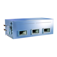
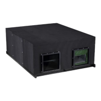
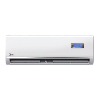
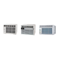
Shows the visual appearance of outdoor units and hydronic boxes.
Details the layout of components within outdoor units for various models.
Illustrates the piping configurations for outdoor and hydronic units.
Depicts refrigerant flow during heating/DHW and cooling/defrosting operations.
Explains the conditions under which the system stops operation.
Details controls for crankcase heater and water pump during standby.
Covers compressor startup delay and startup programs based on ambient temperature.
Describes component control during normal heating, DHW, and cooling operations.
Outlines protections for high/low pressure, temperature, current, and voltage.
Details oil return, defrosting, force cooling, fast DHW, and smart grid controls.
Explains the function and location of various temperature sensors.
Shows the layout of electrical components within control boxes for outdoor and hydronic units.
Details the main PCBs for outdoor units and hydronic systems, including component identification.
Lists error codes, serial numbers, content, and remarks for system faults.
Provides procedures for diagnosing and resolving specific error codes and issues.
Contains supplementary information, such as sensor resistance characteristics.
| Brand | Midea |
|---|---|
| Model | HB-A100/CGN8-B |
| Category | Air Conditioner |
| Language | English |