M thermal Split
202004 35
2 PCBs
2.1 Outdoor Unit PCBqsss
There are one type of main PCB for the 4kW to 16kW models. In addition to the main PCB, all models have an inverter
module.
The locations of each PCB in the outdoor unit electric control box are shown in Figures 4-1.1 to Figure 4-1.4 in Part 4, 1.1
Outdoor Unit Electric Control Box Layout . The locations of each PCB in the hydronic box electric control box are shown in
Figures 4-1.5 in Part 4, 1.2 Hydronic Box Electric Control Box Layout .
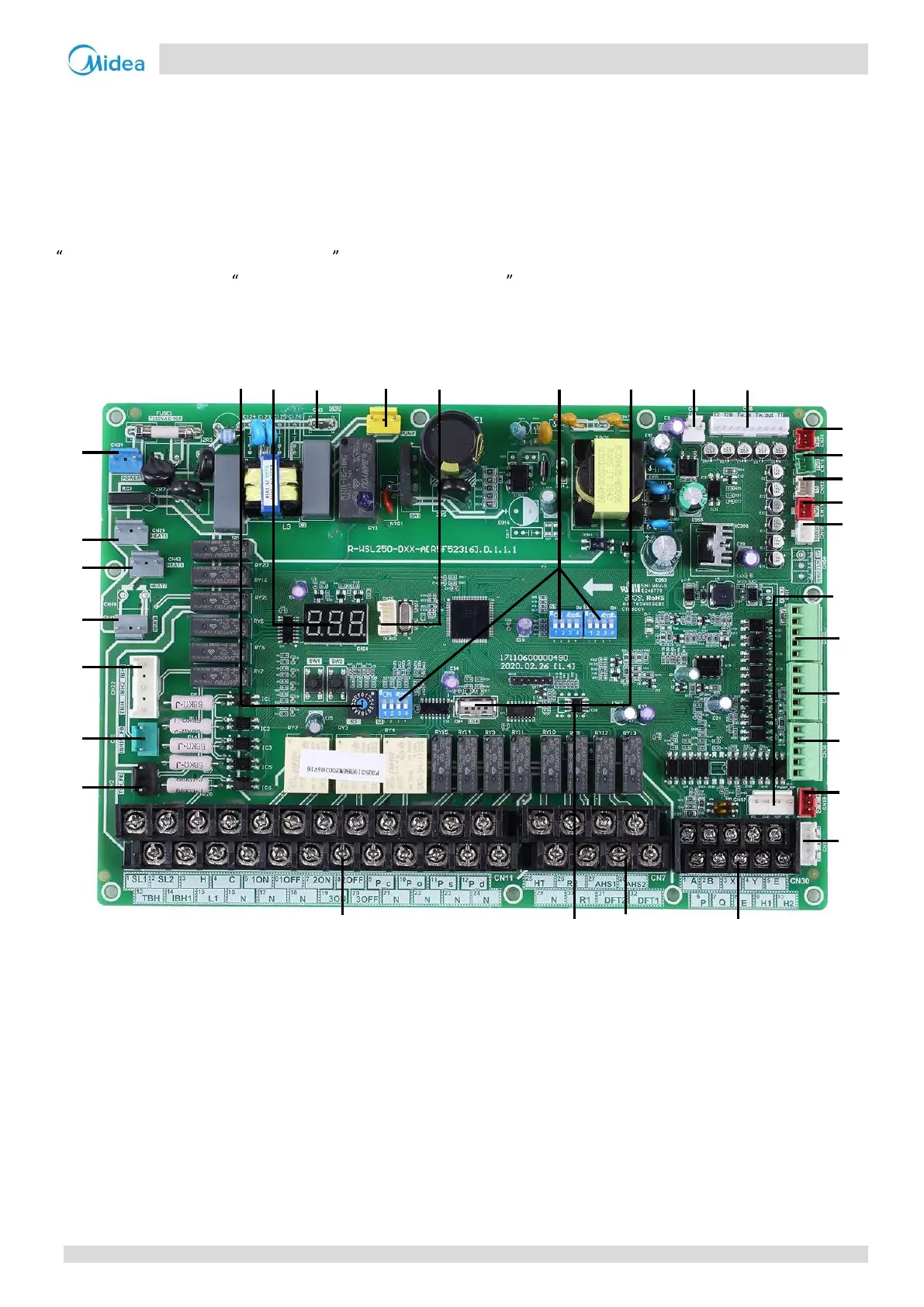
2.2 Main PCB for Hydronic System
Figure 4-2.1: HB-A60(100,160)/CGN8-B hydronic box main PCB
2 3 4 5 6 7 8 9 10
1
30
29
28
27
26
25
11
12
13
14
15
16
17
18
19
20
21
24 31 23 22
22
Midea CAC
 Loading...