Do you have a question about the Midea M-Thermal A Series and is the answer not in the manual?
Details on the capacity range of outdoor units and compatible hydronic box models.
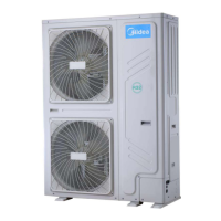
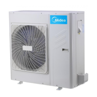
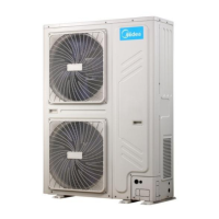
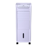
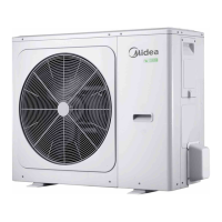
Visual overview of the outdoor unit and hydronic box appearance.
Details on the layout of functional components in outdoor and hydronic units.
Illustrates the piping diagrams for outdoor and hydronic units.
Diagrams showing refrigerant flow during different operating modes.
Describes the reasons and conditions for system stop operations.
Details control logic for crankcase heater and water pump during standby.
Explains compressor startup delay and startup program sequences.
Details component control during normal heating, cooling, and DHW operations.
Covers high/low pressure, temperature, current, and voltage protection mechanisms.
Explains oil return, defrosting, force cooling, and fast DHW operations.
Illustrates the location and function of temperature sensors in system control.
Provides diagrams of the electric control box layouts for outdoor and hydronic units.
Details the main PCBs for outdoor and hydronic systems, including connector labels.
Lists error codes, serial numbers, content, and remarks for system faults.
Guides for diagnosing and resolving specific error codes including inverter and system faults.
Contains supplementary information relevant to Part 4 of the manual.
| Series | M-Thermal A Series |
|---|---|
| Refrigerant | R32 |
| Power Supply | 220-240V, 50Hz |
| Dimensions (Indoor Unit) | Varies by model |
| Weight (Indoor Unit) | Varies by model |
| Dimensions (Outdoor Unit) | Varies by model |
| Weight (Outdoor Unit) | Varies by model |