Do you have a question about the Midea M-Thermal Series and is the answer not in the manual?
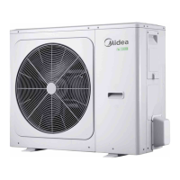
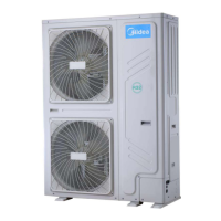
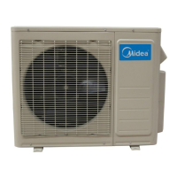
Details outdoor unit and hydronic box model capacities for different kW ranges.
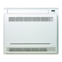
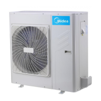
Shows visual representation of outdoor units and hydronic boxes.
Identifies key components within the outdoor and hydronic units.
Illustrates refrigerant and water piping configurations for different system parts.
Depicts refrigerant flow during heating/hot water and cooling/defrosting operations.
Explains conditions under which the system stops operation.
Details controls and operations when the unit is in standby mode.
Describes the processes and parameters for system startup.
Outlines how components are controlled during normal heating/cooling/DHW operations.
Details various protection mechanisms to prevent system damage.
Covers specific operational modes like oil return, defrosting, and force cooling.
Explains the function and location of temperature sensors in system control.
Shows the internal layout of the electric control boxes for outdoor and hydronic units.
Identifies and describes the main PCBs used in the hydronic and outdoor units.
Lists error codes, their content, display locations, and relevant remarks for diagnosis.
Provides general warnings and specific troubleshooting procedures for common error codes.
Contains detailed sensor resistance characteristics for diagnostic purposes.
| Brand | Midea |
|---|---|
| Model | M-Thermal Series |
| Category | Air Conditioner |
| Language | English |