EasyManua.ls Logo

Midea M2OC-18HFN1-M User Manual

Midea M2OC-18HFN1-M
128 pages
To Next Page IconTo Next Page
Page #1 background imageLoading...
Page #1 background image
Multi outdoor units
SERVICE MANUAL
Multi zone
CONDENSING UNITS
Revision B: ODMI-C1-1403
Model Numbers:
M2OC-18HFN1-M M3OC-30HRFN1-M
M2OD-18HFN1-M M4OC-36HRFN1-M
M3OD-27HRDN1-M
WARNING
Installation MUST conform with local building codes or, in the absence of local
codes, with the National Electrical Code NFPA70/ANSI C1-1993 or current edition
and Canadian Electrical Code Part1 CSA C.22.1.
The information contained in the manual is intended for use by a qualified service
technician familiar with safety procedures and equipped with the proper tools and
test instruments
Installation or repairs made by unqualified persons can result in hazards to you
and others.
Failure to carefully read and follow all instructions in this manual can result in
equipment malfunction, property damage, personal injury and/or death.
Table of Contents
1. Product Specifications
2. Indoor Unit Combination
3. Suggested Indoor Unit Model Numbers
4. Dimension Of Outdoor Unit
5. Refrigerant Cycle Diagram
6. Installation Details
7. Electronic Function
8. Wiring Diagrams And Electrical Trouble Shooting
9. Disassembly Instructions
10. Exploded View
Question and Answer IconNeed help?

Do you have a question about the Midea M2OC-18HFN1-M and is the answer not in the manual?

Midea M2OC-18HFN1-M Specifications

General IconGeneral
RefrigerantR410A
Power Supply220-240V, 50Hz
Cooling Capacity18000 BTU/h
Heating Capacity5.6 kW
Operating Temperature (Cooling)18°C to 43°C
Operating Temperature (Heating)-7°C to 24°C

Summary

Condensing Unit Overview

General Safety Warnings

Indoor Unit Combinations

Suggested Indoor Unit Model Numbers

Lists compatible indoor unit models for each outdoor unit.

Outdoor Unit Dimensions

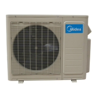
Provides physical dimensions for various outdoor unit models.

Refrigerant Cycle Diagrams

Illustrates refrigerant flow for different unit configurations.

Installation Procedures

Wrench Torque Specifications

Specifies torque values for pipe connections during installation.

Cable Connection Guidelines

Details power and communication cable connection requirements.

Piping Length and Elevation Limits

Outlines maximum allowed pipe length and height differences.

First-Time Installation

Step-by-step guide for initial system setup and preparation.

Refrigerant Charging

Instructions for evacuating, purging, and charging refrigerant.

Re-installation

Procedures for reinstalling units after repair.

Electronic Functions and Controls

Abbreviation Glossary

Defines technical terms and abbreviations used in the manual.

Control System Environment

Specifies operating voltage, frequency, and fan amp limits.

Protection Mechanisms

Details safety features like delay timers, temperature, and current protection.

Wiring Diagrams

1 Drive 2 Outdoor Unit Wiring

Electrical schematic for 1-drive-2 outdoor unit configurations.

PCB Board Layouts

Diagrams showing component placement on various PCB boards.

IPM Board Diagrams

Schematics for the Intelligent Power Module (IPM) boards.

Troubleshooting Guide

Safety Precautions

Essential safety guidelines for handling electrical components.

Indoor Unit Error Codes

Lists error codes and their corresponding failures for indoor units.

Outdoor Unit Error Codes

Lists error codes and their corresponding failures for outdoor units.

Diagnosis and Solution Flowcharts

Step-by-step guides for diagnosing and resolving common malfunctions.

Disassembly Instructions

Panel Plate Removal

Procedures for removing the outer panel of specific outdoor unit models.

Fan Assembly Removal

Steps to remove and replace the fan motor assembly.

Electrical Parts Removal

Instructions for safely removing IPM boards, reactors, and compressors.

Compressor Removal

Detailed steps for removing the compressor unit.

Valve Removal

Procedures for detaching the 4-way valve and expansion valve.

Related product manuals