M‐ThermalSplit
12201909
MideaM‐ThermalSplitServiceManual
2.2 HydronicboxPiping
SMK‐60/CGN8/SMK‐80/CGN8
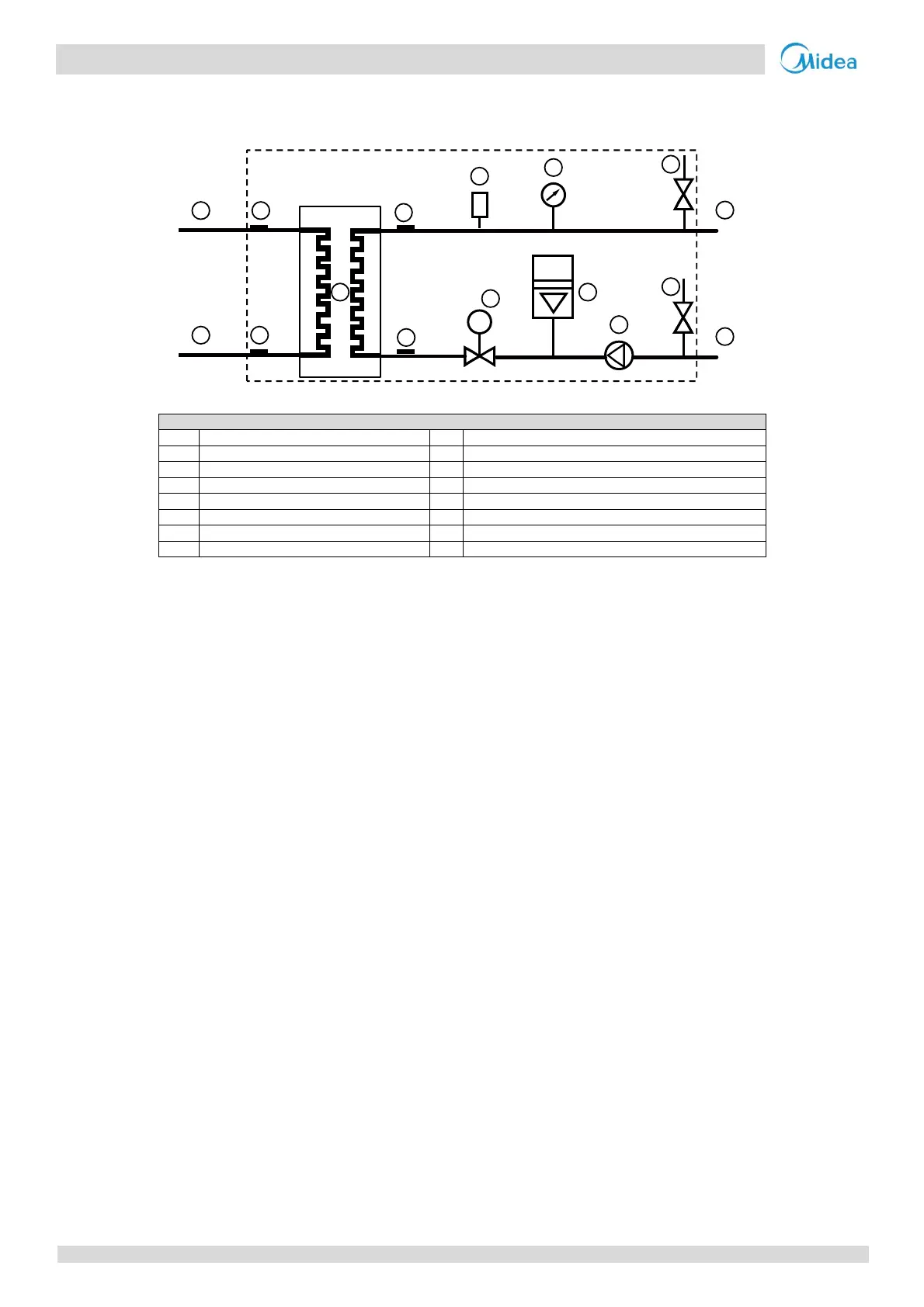
Figure2‐2.2:SMK‐60/CGN8/SMK‐80/CGN8pipingdiagram
Legend
1 Watersideheatexchanger 9 Waterpump
2 Waterflowswitch 10 Manometer
3 Refrigerantliquidlinetemperaturesensor 11 Safetyvalve
4 Refrigerantgaslinetemperaturesensor 12 Refrigerantgas side
5 Wateroutlettemperaturesensor 13 Refrigerantliquidside
6 Waterinlettemperaturesensor 14 Wateroutlet
7 Airpurgevalve 15 Waterinlet
8 Expansionvessel
Keycomponents:
1. Airpurgevalve:
Automaticallyremovesairfromthewatercircuit.
2. Safetyvalve:
Preventsexcessivewaterpressurebyopeningat43.5psi(3bar)anddischargingwaterfromthewatercircuit.
3. Expansionvessel:
Balanceswatersystempressure.(Expansionvesselvolume:3L.)
4. Waterflowswitch:
Detectswaterflowratetoprotectcompressorandwaterpumpintheeventofinsufficientwaterflow.
5. Backupelectricheater:
Providesadditionalheatingcapacitywhentheheatingcapacityof the heat pump is insufficient due to very low
outdoortemperature.Alsoprotectstheexternalwaterpipingfromfreezing.
6. Manometer:
Provideswatercircuitpressurereadout.
7. Waterpump:
Circulateswaterinthewatercircuit.
2
11
3
4
5
6
7
1 8
9
10
12
11
13
14
15
F
 Loading...