Refrigerant pipe installation
96 Installation
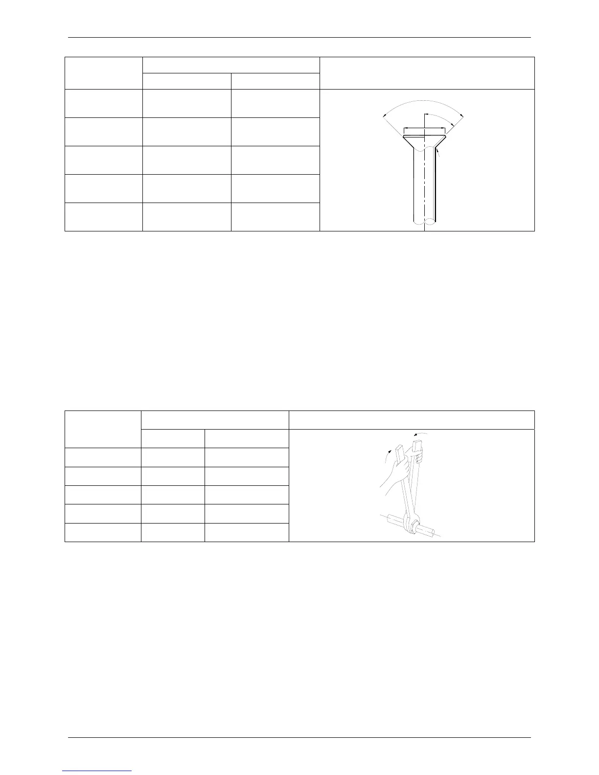
Pipe diameter
Flare dimension A (mm)
Flare shape
Min Max
1/4" (6.35) 8.3 8.7
R0.4~0.8
A
4
5
°
90°
4
-
+
3/8" (9.52) 12.0 12.4
1/2" (12.7) 15.4 15.8
5/8" (15.9) 18.6 19.1
3/4" (19) 22.9 23.3
After flared the pipe, the opening part must be seal by end cover or adhesive tape to avoid duct or
exogenous impurity come into the pipe.
5.2.7 Drill holes if the pipes need to pass the wall.
5.2.8 According to the field condition to bend the pipes so that it can pass the wall smoothly.
5.2.9 Bind and wrap the wire together with the insulated pipe if necessary.
5.2.10 Set the wall conduit
5.2.11 Set the supporter for the pipe.
5.2.12 Locate the pipe and fix it by supporter
For horizontal refrigerant pipe, the distance between supporters should not be exceed 1m.
For vertical refrigerant pipe, the distance between supporters should not be exceed 1.5m.
5.2.13 Connect the pipe to indoor unit and outdoor unit by using two spanners.
Be sure to use two spanners and proper torque to fasten the nut, too large torque will damage the
bellmouthing, and too small torque may cause leakage. Refer the following table for different pipe
connection.
Pipe Diameter
Torque Sketch map
(kgf.cm) (N.cm)
1/4" (6.35) 144~176 1420~1720
3/8" (9.52) 333~407 3270~3990
1/2" (12.7) 504~616 4950~6030
5/8" (15.9) 630~770 6180~7540
3/4" (19) 990~1210 9270~11860
5.3 For Units with Twins Function
5.3.1 Length and drop height permitted of the refrigerant piping
Note: Reduced length of the branching tube is the 0.5m of the equivalent length of the pipe.
 Loading...