V4+R VRF 50/60Hz
26 201702
Midea V4+R Series Service Manual
4 Startup Control
4.1 Compressor Startup Delay Control
In initial startup control, compressor startup is delayed for 12 minutes in order to let the master unit search for the indoor
units’ addresses. In restart control (except in oil return operation and defrosting operation), compressor startup is delayed
such that a minimum of 7 minutes has elapsed since the compressor stopped, in order to prevent frequent compressor
on/off and to equalize the pressure within the refrigerant system.
4.2 Startup Control for Cooling Operation
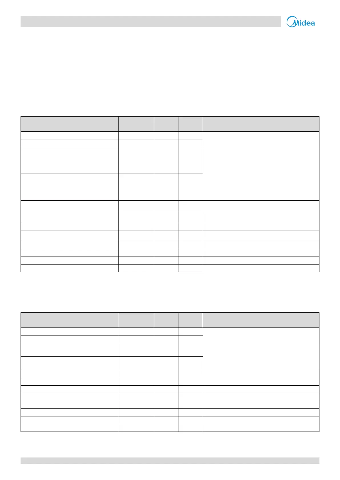
Table 3-4.1: Component control during startup in cooling mode
Control functions and states
Controlled according to load requirement, operating
frequency increased by 1 step / sec
Fan speed
1
controlled according to discharge
pressure (P
c
):
At initial speed for 90 seconds.
Subsequently, P
c
checked every 10 seconds:
P
c
≥ 2.7MPa, => 1 step increase.
P
c
≤ 2.1MPa => 1 step decrease.
Electronic expansion valve A
Position (steps) from 0 (fully closed) to 480 (fully
open), controlled according to discharge
temperature
Electronic expansion valve B
Solenoid valve (liquid refrigerant injection)
Solenoid valve (oil balance)
Closed for 200 secs, open for 600 secs, then closed
Solenoid valve (fast defrosting)
Notes:
1. Refer to Table 3-5.3 in Part 3, 5.6 “Outdoor Fan Control” for more information on fan speed steps.
4.3 Startup Control for Heating Operation
Table 3-4.2: Component control during startup in heating mode
Control functions and states
Controlled according to load requirement, operating
frequency increased by 1 step / sec
Open once the four-way valve has opened,
controlled according to outdoor ambient
temperature and load requirement
Electronic expansion valve A
Position (steps) from 0 (fully closed) to 480 (fully
open), controlled according to discharge superheat
Electronic expansion valve B
Solenoid valve (liquid refrigerant injection)
Solenoid valve (oil balance)
Closed for 200 secs, open for 600 secs, then closed
Solenoid valve (fast defrosting)
Notes:
1. Refer to Table 3-5.3 in Part 3, 5.6 “Outdoor Fan Control” for more information on fan speed steps.



 To Next Page