MCAC-VTSM-2016-10 R410A All DC Inverter Mini VRF
Troubleshooting 89
Condition 2: L0 error appears immediately when the compressor starts up.
Notes:
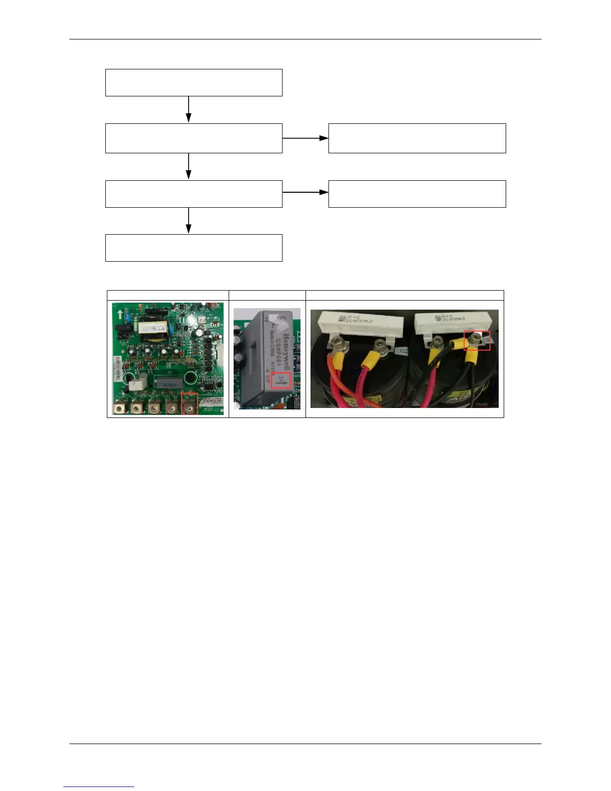
1. The DC bus wire should run from the N terminal on the inverter module, through the current sensor (in the direction indicated by the
arrow on the current sensor), and end at the N terminal of capacitor.
2. To check for compressor:
The normal resistances of the inverter compressor are 0.7-1.5Ω among U V W and infinite between each of U V W and ground. If
any of the resistances differ from these specifications, the compressor has malfunctioned.
If there is another unit nearby that is operating normally, its electric control box can be used to check the compressor. Disconnect
the power wires of the compressor referenced in the error unit and also disconnect the power wires that connect the compressor to
the electric control box in the normal unit and use them to connect the compressor in error unit to the electric control box of the unit
that is operating normally. Ensure that the U, V, W terminals are connected in the right order, and then start the system that is
operating normally. If the compressor in error unit runs normally means the compressor is normal; if the compressor still does not
run normally means the compressor has malfunctioned.
 Loading...