Page 29
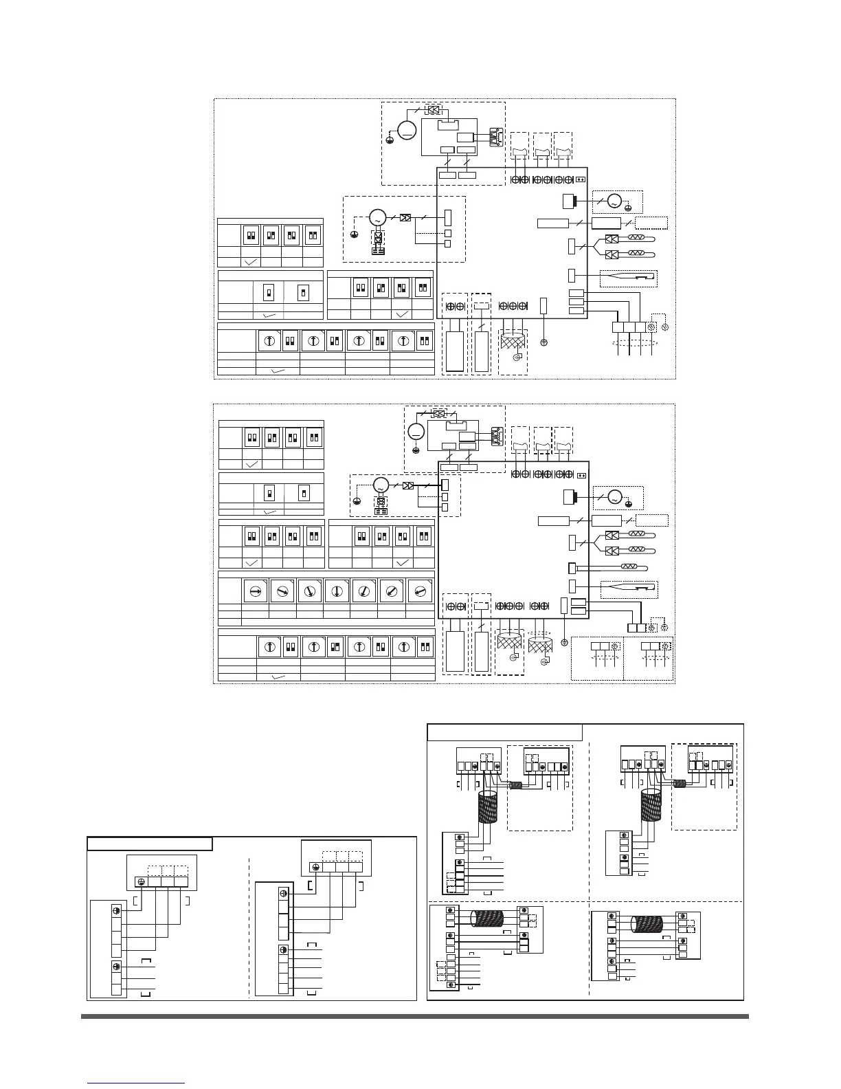
Wiring diagram
Connective wiring diagram
Air Condition Link-Circuit
Power supply:
1-Phase 220-240V~
Use 3-core cable(14AWG)
for the models which with
auxiliary electric heater(PTC);
Use 3-core cable(16AWG)
for the others.
Power supply:
1-Phase 220-240V~
Use 3-core cable(14AWG)
for the models which with
auxiliary electric heater(PTC);
Use 3-core cable(16AWG)
for the others.
INDOOR UNIT
S1
S2
P
Q
INDOOR UNIT
P
Q
S1
S2
L2
L1
L2
L1
L1
L2
L3
N
S1
S2
A
B
C
OUTDOOR UNIT
2-core shielded cable(24AWG)
Power supply:
1-Phase 220-240V~
Use 3-core cable(14AWG)
for the models which with
auxiliary electric heater(PTC);
Use 3-core cable(16AWG)
for the others.
Power supply:
1-Phase 220-240V~
Use 3-core cable(14AWG)
for the models which with
auxiliary electric heater(PTC);
Use 3-core cable(16AWG)
for the others.
INDOOR UNIT
P
Q
S1
S2
L2
L1
INDOOR UNIT
S1
S2
P
Q
L2
L1
OUTDOOR UNIT
S1
S2
L2
L1
Power supply:3-Phase 380-415V~
30K-60K: 5-core cable(14AWG)
Power supply:3-Phase 220V~
30K-60K: 5-core cable(12AWG)
Power supply:1-Phase 220-240V~
18K: 3-core cable(14AWG)
19K-36K: 3-core cable(12AWG)
37K-60K: 3-core cable(10AWG)
L1
L2
L3
N
S1
S2
A
B
C
OUTDOOR UNIT
INDOOR UNIT
S1
S2
L2
L1
2
Use 3-core cable(14AWG)
for the models which with
auxiliary electric heater(PTC);
Use 3-core cable(16AWG)
for the others.
OUTDOOR UNIT
S1
S2
INDOOR UNIT
S1
S2
L2
L1
Use 3-core cable(14AWG)
for the models which with
auxiliary electric heater(PTC);
Use 3-core cable(16AWG)
for the others.
(1)L1
(2)L2
L2
L1
Q
P
Q
P
2-core shielded cable(24AWG)
2-core shielded
cable(24AWG)
Power supply:1-Phase 220-240V~
18K: 3-core cable(14AWG)
19K-36K: 3-core cable(12AWG)
37K-60K: 3-core cable(10AWG)
Power supply:3-Phase 380-415V~
30K-60K: 5-core cable(14AWG)
Power supply:3-Phase 220V~
30K-60K: 5-core cable(12AWG)
(1)L1
(2)L2
2-core shielded
cable(24AWG)
INDOOR UNIT
1 2
3
L1 L2 S
INDOOR UNIT
Air Condition Link-Circuit
OUTDOOR UNIT
Power supply:3-Phase 380-415V~
5-core cable (14AWG)
Power supply:3-Phase 220V~
5-core cable (12AWG)
L1
L2
L3
N
OUTDOOR UNIT
Power supply:
1-Phase 208-240V~
≤24K : 3-core cable (14AWG)
25K-36K : 3-core cable (12AWG)
≥37K : 3-core cable (10AWG)
4-core cable (16AWG)
4-core cable (14AWG)
(with auxiliary electric heater)
4-core cable (16AWG)
4-core cable (14AWG)
(with auxiliary electric heater)
1 2
3
L1 L2 S
1 2
3
L1 L2
1 2
3
0
8
4
1
2
3
5
6
7
C
9
A
B
D
E
F
1
2
ON
0
8
4
1
2
3
5
6
7
C
9
A
B
D
E
F
1
2
ON
0
8
4
1
2
3
5
6
7
C
9
A
B
D
E
F
1
2
ON
0
8
4
1
2
3
5
6
7
C
9
A
B
D
E
F
1
2
ON
S1+S2
0~F 0~F 0~F
0~F
NETADDR ESS
CODE
0~15
16~31
32~47 48~63
FA C T O R Y S E T T I N G
FOR SET TING NETADDRE SS
INDOOR UNIT
MAINBOARD
CN33
ALARM
Alarm
Outpu t
16023000007041
WIRING DIAGRAM
(INDOOR UNIT)
DISPL AY
BOARD
WIRE
CONT ROLLE R
10
CN10
5
1
2
ON
1
2
ON
1
2
ON
1
2
ON
EEPROM
DEFAULT
FACTORY
SETT ING
FOR TEMP. CO MPENS ATION( HEATIN G)
SW6
CODE
6℃
2℃
4℃
T2
T1
CN6
4
BLACK
WHITE
INDOOR COIL TEMP. SENSOR
ROOM TEMP. SENSOR
CN40
WIRE
CONTR OLLER
4
CN5
WATER LEVEL SWITCH
CN9
X Y E
To CCM
Comm .Bu s
HB HA
CN45
WIRE
CONTR OLLER
Y/G
CN18
J7
CN23
ON/OFF
Remot e
Contr ol
CN43
FAN FOR THE
FRESH AIR
OR ANION
GENERATOR
NOTE:
1.The parts with dotted line indicates
optional features.
2.Remove the short connector of J7
when you use the "on-off" function.
AC FAN
CAP
Y/G
WHITE
WHITE
(GRAY)
CN4
P1
P2
BLACK
BROWN
M
5
3
1
2
ON
1
2
ON
1
2
ON
1
2
ON
SW1
TEL0
24℃
15℃
8℃
EEPROM
DEFAULT
FACTORY
SETT ING
FOR ANTI -COLD WIN D
1
ON
1
ON
FACTORY SETTI NG
FOR SET TING AUTO-RES TART
FOR SET TING AUTO-RES TART
SW3
MODE
AUTO -R ES TART
NOT AUTO-RES TART
RED
CN2
CN1
BLACK
CN3
YELLO W(WHITE )
TO OUTDOOR UNIT
Y/G
1
2 3
Reactor
CON2
RED
RED
DC MOTOR
DRIVER M ODLE
CON1
FAN1
3
3
M
4
CN1
CN15
CN34
DC FAN
Y/G
MAGNETIC
RING
CN13
M
PUMP
2
Y/G
18K and 24K
36K and 48K
18K and 24K
36K and 48K
0
8
4
1
2
3
5
6
7
C
9
A
B
D
E
F
1
2
ON
0
8
4
1
2
3
5
6
7
C
9
A
B
D
E
F
1
2
ON
0
8
4
1
2
3
5
6
7
C
9
A
B
D
E
F
1
2
ON
0
8
4
1
2
3
5
6
7
C
9
A
B
D
E
F
1
2
ON
S1+S2
0~F 0~F 0~F
0~F
NETADDR ESS
CODE
0~15
16~31
32~47 48~63
FA C T O R Y S E T T I N G
FOR SET TING NETADDRE SS
INDOOR UNIT
MAINBOARD
16023000007021 WIRING DIAGRAM
DI SPL AY
BO ARD
WIRE
CONT ROLLE R
10
CN10
5
0
8
4
1
2
3
5
6
7
C
9
A
B
D
E
F
0
8
4
1
2
3
5
6
7
C
9
A
B
D
E
F
0
8
4
1
2
3
5
6
7
C
9
A
B
D
E
F
0
8
4
1
2
3
5
6
7
C
9
A
B
D
E
F
0
8
4
1
2
3
5
6
7
C
9
A
B
D
E
F
0
8
4
1
2
3
5
6
7
C
9
A
B
D
E
F
0
8
4
1
2
3
5
6
7
C
9
A
B
D
E
F
ENC1
4
5
7
8
9
A
B
POWER
CODE
≤53
54~71
72~90
91~105
106~140
141~160
≥161
FA C T O R Y
SE T T I N G
ACCORDIN G TO RELATED MODEL.
FOR SET TING POWE R(DC M OTOR MODE L ONLY )
1
2
ON
1
2
ON
1
2
ON
1
2
ON
SW1
TEL0
24℃
15℃
8℃
EEPROM
DEFAULT
FACTORY
SETT ING
FOR ANTI -COLD WIN D
1
2
ON
1
2
ON
1
2
ON
1
2
ON
EEPROM
DEFAULT
FACTORY
SETT ING
FOR TEMP. CO MPENS ATION( HEATIN G)
SW6
CODE
6℃
2℃
4℃
RE D
CN2
CN1
BL ACK
1
ON
1
ON
FACTORY SETTI NG
FOR SET TING AUTO-RES TARTFOR SET TING AUTO-RES TART
SW3
MODE
AUTO -R ES TART
NOT AUTO-RES TART
T2
T1
CN6
4
BLACK
WHITE
T2B
CN7
INDOOR COIL OU TLET TEMP. SENSOR
INDOOR COIL TEMP. SENSOR
ROOM TEMP. SENSOR
Y/G
CN18
CN40
WI RE
CO NTR O LLE R
4
CN5
WATER LEVEL SWITCH
CN9
X Y E
TO OUTDOO R
COMM. BUS
To CCM
Comm .Bu s
S2 S1
CN20
HB HA
CN 4 5
WI RE
CO NTR O LLE R
MAGNETIC
RING
CN33
AL A RM
ALAR M
OUTP UT
J7
CN23
ON / OFF
REMO TE
CONT ROL
CN43
FAN FOR THE
FRESH AIR
OR ANION
GENERATOR
NOTE:
1.The parts with dotted line indicates
optional features.
2.Remove the short connector of J7
when you use the "on-off" function.
1
2
ON
1
2
ON
1
2
ON
1
2
ON
FACTORY
SETT ING
SW5
MO D E
MAINMAIN SLAVE
MAI N
NO SL A V E
FO R M A IN -S LA VE S ET TI NG
L1
L2
Y/G
TO OUTDOOR UNIT
FOR OUTDOOR POWER SUPPLY
POWER
FAN
CAP
Y/G
WHITE
WHITE
(GRAY)
CN4
P1
P2
BLACK
BROWN
M
5
3
CN34
CN13
M
PUMP
2
Y/G
REACT OR
CON2
RED
RED
DC MOTO R
DRIVER MODLE
CON1
FAN1
3
3
4
CN1
CN15
FAN
M
3
Y/G
MAGNETIC
RING
MAGNETIC
RING
L1
L2
L1
L2
 Loading...