MCAC-2008-11 Air-cooled Modular Chiller
43
12.3 Wiring Installation
All wiring installation should be done by qualified person.
12.3.1 Precautions:
1. The power supply must be stable when the unit is running. Considering all voltage-drop factors, the
running voltage needed by the system should be kept within ±10% range of the rating. Too high or too low
voltage will have bad effect on the unit.
2. The difference of voltage among phases should be not more than 2% of the rating, and the max current
difference among phases should be less than 3% the rating to prevent compressor from overheating.
3. The frequency of the power should be kept within ±2%of the rating.
4. The lowest starting voltage should be more than 90% of the rating.
5. The compressor may be unable to start if the wire is too longer, so the length of the wire should be limited
to ensure the voltage-drop between the two ends of the wire is less than 2% of the rating. If it is unavailable
to shorten the wire, thicker wire is available.
6. All wire must conform to concerning national standards and well insulated. The insulation between
terminals and modules should be checked by 500v high resistance meter and its insulation resistance
should be not less than 10 MΩ.
7. For safety, according to the concerning standards, unit should be grounded well to prevent electric shock.
8. The running current, input power and other parameters on the nameplate might be different from the
actual situation, which is decided by the actual load and cooling water temp., so it is recommended to select
power source, transformer, fuse switch and the size of the wire in the consideration of the worst condition.
9. In order to control the compressors conveniently as well as independently and avoid the damage caused
by the short circuit, it is necessary to equip the suitable no-fuse air switch for each inlet wire.
10. For 30KW & 65 KW, One module consists of two units, each unit’s main power should be wired
independently and the detail is shown as follow:
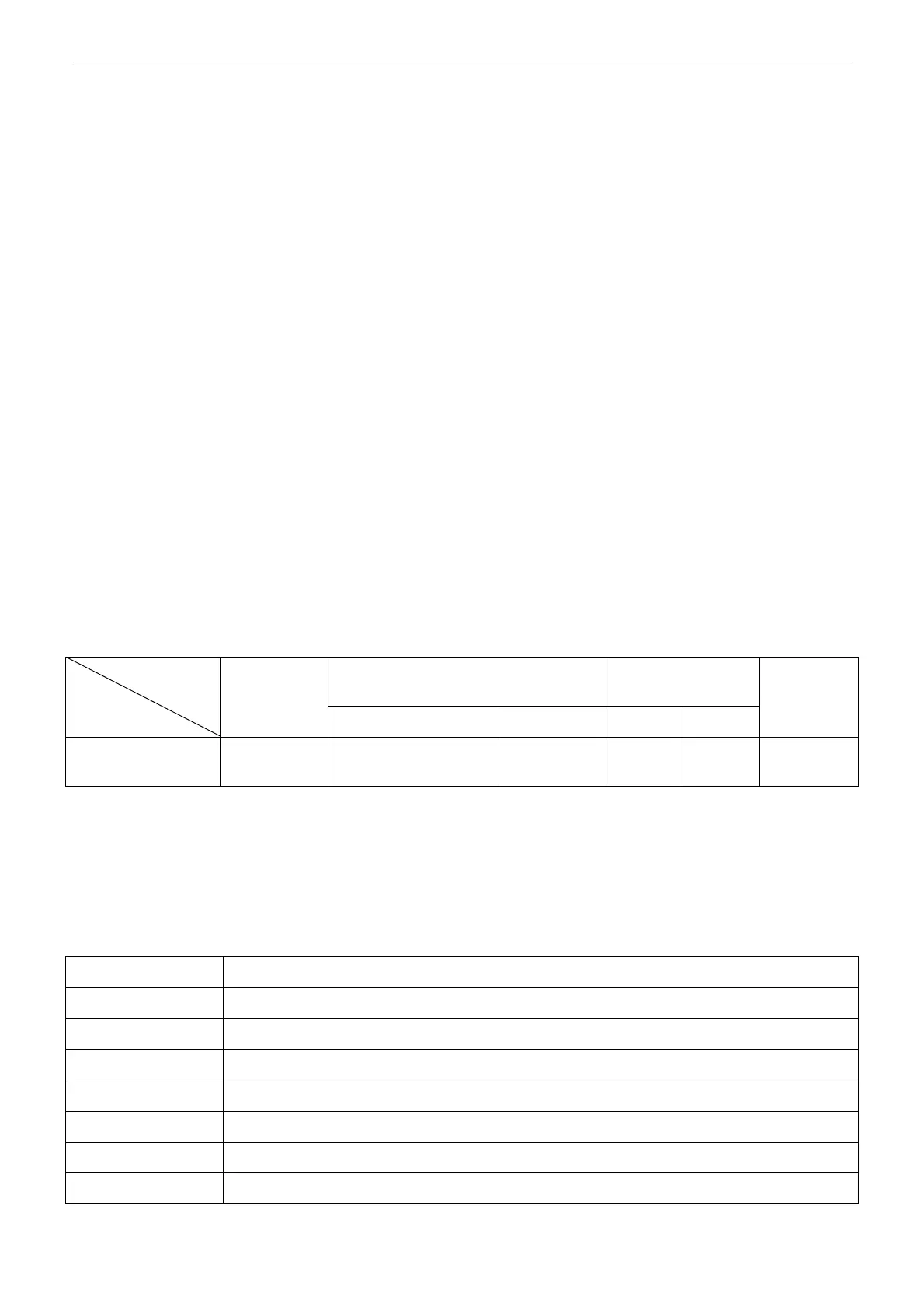
The minimal diameter Of wire (mm
2
)
(metal tube, vinylite)
Manual switch(A)
Items
Model
Power
Power wire(<30m) Grounding Volume Fuse
Creepage
protector
30kW module
65kW module
380V 3N~
50Hz
10 10 50 36 100mA
11. Any part of wiring cannot be exposed when wiring is connected to the terminal.
12. Leak electric switch must be set in power supply system of every module unit.
13. The control signal wiring must use two-cores shielded twisted-pair(KVVP 1mm
2
or RVVP 1mm
2
). Don’t
use many-cores wiring (above 3 cores), otherwise the weak signal would be distributed, especially in the
place with inverter equipments.
12.3.2 Wiring Specification
1. Category of common wiring.
Wiring model Description
RV Cooper core, PVC insulation, tabulate soft wiring
BVV Fix, lay, cooper core, PVC insulation, PVC jacket cable
RVV Cooper core, PVC insulation, PVC jacket, circular soft cable
RVVB Cooper core, PVC insulation, PVC jacket, tabulate soft cable
RVVP Cooper core, PVC insulation, PVC jacket, screened soft cable
KVV-C Cooper core, PVC insulation, PVC jacket, control cable
KVVP Cooper core, PVC insulation, PVC jacket, screened control cable
 Loading...