EasyManua.ls Logo

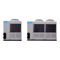
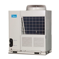
Midea MGA-D30W/SN1

Midea MGA-D30W/SN1
72 pages
To Next Page IconTo Next Page
Loading...
MCAC-2008-11 Air-cooled Modular Chiller
1
Contents
1. Nomenclature…………..………………………………………………...
2. Product Schedule………………………………………………………..
3. Features…………………………………………………………………...
4. Specification……………………………………………………………...
5. Dimension…………………………………………………………………
6. Piping Diagrams & Pipe Connection Drawing……………………...
7. Wiring Diagrams……………………….………………………………..
8. Electric Characteristics…………………………………………….......
9. Capacity Tables…………………………………………………………
10. Exploded View………………………………………………………….
11. Troubleshooting……………..…………………………………………
12. Installation……………………………..………………………………..
13. Debugging...…………………………..………………………………
14. Maintenance…..…………………………..……………………………
15. Control……………………………..…………………………………….
Manufacture reserves the right to discontinue, or change at any time, specifications or designs without
notices and without incurring obligations.

Questions and Answers:

Midea MGA-D30W/SN1 Specifications

General IconGeneral
BrandMidea
ModelMGA-D30W/SN1
CategoryChiller
LanguageEnglish

Summary

Capacity Tables

9.1 Cooling

Cooling capacity data for MGA-F30W/SN1 and MGA-D30W/SN1 models.

9.1 Cooling (Continued)

Cooling capacity data for MGA-F65W/SN1 and MGA-D65W/SN1 models.

9.2 Heating

Heating capacity data for MGA-F30W/SN1 and MGA-D30W/SN1 models.

9.2 Heating (Continued)

Heating capacity data for MGA-F65W/SN1 and MGA-D65W/SN1 models.

Troubleshooting

11.1 Failure & Protection Codes of the Module

Lists failure and protection codes for the module with their descriptions.

11.2 Troubles and Solutions

Provides common troubles and their possible reasons and solutions.

Troubles and Solutions (Continued)

Lists common troubles, possible reasons, and solutions.

Wiring Installation

12.3.1 Precautions

Important precautions to follow during wiring installation.

12.3.2 Wiring Specification

Specifies wiring categories and common wiring models.

2. Specification of Control Wiring

Details specifications for control wiring, including length and type.

4. Power Wiring

Covers categories and diameter selection for power wiring.

Testing

1. Preparation

Preparation steps before performing unit testing.

1) Unit Address Setting

Instructions for setting the unit address switch.

2) Digital Scroll Modular and Normal Scroll Modular Selection

How to select between digital and normal scroll modular types.

2. Testing

Performing the unit testing procedure.

4) Optimizing the Setting Parameters

Optimizing setting parameters based on local conditions.

5) After the Unit Stops

Checks to perform after the unit has stopped.

Maintenance

Warning

Critical warnings regarding fire and flammable gases.

Caution

General cautions for maintaining the unit's condition.

Maintenance for Main Components

Guidance on maintaining key components of the unit.

Refrigeration System

Procedures for refrigerant handling, leakage testing, and charging.

System Anti-freeze

Precautions and procedures to prevent freezing issues in the system.

Control System

15.1 PCB Outline and Description

Overview and description of the PCB layout for 30kW and 65kW modules.

15.1.1 PCB, Outlook View (30 kW & 65 kW Module)

Visual layout of the PCB with numbered components.

15.1.2 Components Description of 30 kW & 65 kW Module

Description of specific PCB components and their functions.

9-ADDRESS

Instructions for setting the unit's address for modular systems.

12-System A High-Pressure Protection & Discharge Gas Temperature Switch Protection

Explains high-pressure and discharge gas temperature protection for System A.

Module Failure & Protection Codes

Controllers

15.3.1 Wired Controller: KJR-08 BBE

Introduces the wired controller model and its keypad layout.

Name of Keys on the Wired Controller and the Keypad Operation Description

Explains the function of each key on the wired controller.

4. QUERY Button

Explains how to query unit status information.

Wired Controller LCD Screen Functions

Installation Procedure

Details the wiring procedure and principles for controller installation.

Wired Controller Operation Procedures

Unit Information Query Procedure

Fault Alarm Handling

Explains how fault alarms are indicated and handled.

CCM10 LCD Touch Screen (Optional)

Electrical Installation

Details electrical interface and wiring for the LCD touch screen.

Operation Description of LCD Touch Screen

Describes the base conditions and operation of the LCD touch screen.

Function Description

Explains the overall function and configuration of the LCD control system.

LCD Operation Window

Shows the principal window of the LCD interface.

Query Window Operation

Mode Setting Window

Malfunction Queried Window

How to query malfunctions and access troubleshooting help.

Electricity Control Functions

Query Function

Detailed explanation of the query function and navigation.

Mode Setting Function

Detailed explanation of mode setting and unit quantity control.

Operation and Control Mode Settings

Operation Mode and Control Mode Setting

Related product manuals