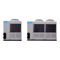
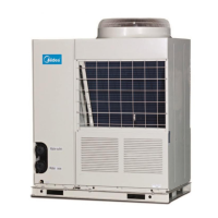
MCAC-2008-11 Air-cooled Modular Chiller
58
125 for 10 minutes. If DLT is lower than 125 , protection will eliminate, on the other hand, if DLT keeps ℃℃
increasing to 140 or more, it ℃ enter red area when the compressor stop and restart 3 minutes later if the
problem has been solved.
13——Anti-frost protection sensor of plate exchanger T6, T62.
14——Water flow check (failure code E0 for main unit) which is just valid for main unit.
z Main unit: main unit controller displays E9 when water flow is abnormal first time and second time and
displays E0 when water flow is abnormal third time. (Display resumes after cutting power supply). Wire
controller also displays E0 after three times’ checking.
z Auxiliary: without water flow checking.
15——System B electric expansion valve.
16——System A electric expansion valve.
EXV can adjust the refrigerant flow according to different running models and capacity requested by
surrounding.
17——HEAT auxiliary heater.
Notice: the actual figure of controller of the heater is not 220V power supply but ON/OFF switch!
On heating mode, when the total outlet water temperature is below 45 , the switch closes and auxiliary ℃
heater starts working; on the other hand, when the Temperature is above 50 , the switch opens to stop ℃
heating and heater stops working.
18——WATER PUMP
Notice: the actual figure of controller of the pump is not 220V power supply but ON/OFF switch!
z Water pump will start at once after receiving the opening order and keep running during the whole
running term of the system. Pump will close 2 minutes later after all the units having been shut down on
cooling or heating mode.
z Pump can be closed directly on the pump mode.
19——System B compressor
Ground wire
System B four-way valve
Ground wire
20——Digital tube
z On waiting mode: display unit address.
z On running mode:
z Main unit display the current capacity of the digital compressor as 40, 60, 80 and 10. (Notice “10” is
followed by “.”)
z Auxiliary unit display 10. (Notice “10” is followed by “.”)
z On failure or protection mode: display failure code or protection code.
21——System A compressor;
Earth wire
Four-way valve of system A
Earth wire
22——High speed of outdoor fan, controlled by T4.
23——Low speed of outdoor fan, controlled by T4.
24——PWM, used for digital compressor capacity adjustment. (It is valid for main unit).
25——Transformer input, 220V/AC.
26——Power input by three-phase four-wire system (E1 for failure code).
A, B, C phases should be supplied together with the 120 degree angle difference among three phases. If it
is not qualified, it may cause phases sequence failure or phases absent failure then the corresponding code
will be displayed until the power get right. Notice: phases sequence failure or phases absent failure are just

 Loading...


