Air-cooled modular chiller unit 50Hz MCAC-ATSM-2011-12
116
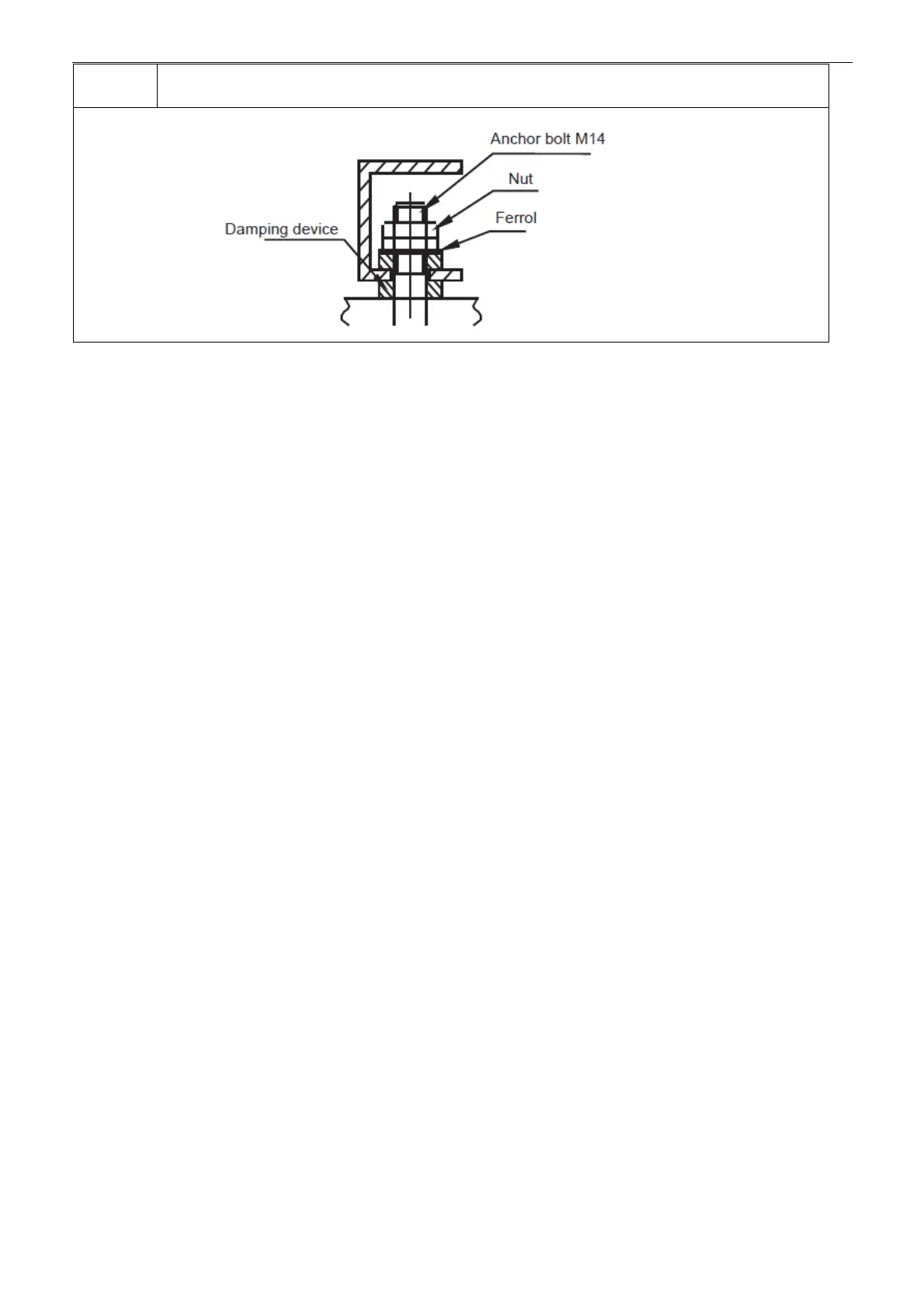
6 The lock bolts can be tightened after the correct operational height is reached.
12.2 Water System Installation
Notice:
● After the unit is in place, chilled water pipes can be laid.
● The relevant installation regulations should be abided with when conducting connection of water pipes.
● The pipelines should be free of any impurity, and all chilled water pipes must conform to local rules and
regulations of pipeline engineering.
12.2.1 Connection requirements of chilled water pipes
a. All chilled water pipelines should be thoroughly flushed, to be free of any impurity, before the unit is
operated. Any impurity should not be flushed to or into the heat exchanger.
b. Water must enter the heat exchanger through the inlet; otherwise the performance of the unit will decline.
c. The inlet pipe of the evaporator must be provided with a target flow controller, to realize flow-break
protection for the unit. Both ends of the target flow controller must be supplied with horizontal straight pipe
sections whose diameter is 5 times that of the inlet pipe. The target flow controller must be installed in strict
accordance with “Installation & Regulation Guide for Target Flow Controller”. The wires of the target flow
controller should be led to the electric cabinet through shielded cable. The working pressure of the target
flow controller is 1.0MPa, and its interface is 1 inch in diameter. After the pipelines are installed, the target
flow controller will be set properly according to the rated water flow of the unit.
d. The pump installed in the water pipeline system should be equipped with starter. The pump will directly
press water into the heat exchanger of the water system.
e. The pipes and their ports must be independently supported but should not be supported on the unit.
f. The pipes and their ports of the heat exchanger should be easy to disassemble for operation and cleaning,
as well as inspection of port pipes of the evaporator.
g. The evaporator should be provided with a filter with more than 40 meshes per inch at site. The filter
should be installed near to the inlet port as much as possible, and be under heat preservation.
h. The by-pass pipes and by-pass valves as shown in the figure of “Connection drawing of pipeline
system” must be mounted for the heat exchanger, to facilitate cleaning of the outside system of water
passage before the unit is adjusted. During maintenance, the water passage of the heat exchanger can be
cut off without disturbing other heat exchangers.
i. The flexible ports should be adopted between the interface of the heat exchanger and on-site pipeline, to
reduce transfer of vibration to the building.
j. To facilitate maintenance, the inlet and outlet pipes should be provided with thermometer or manometer.
The unit is not equipped with pressure and temperature instruments, so they need to be purchased by the
user.
k. All low positions of the water system should be provided with drainage ports, to drain water in the
evaporator and the system completely; and all high positions should be supplied with discharge valves, to
facilitate expelling air from the pipeline. The discharge valves and drainage ports should not be under heat
preservation, to facilitate maintenance.
 Loading...