MCAC-ATSM-2011-12 Air-cooled modular chiller unit 50Hz
173
3. INSTALLATION PROCEDURE
Installation procedure:
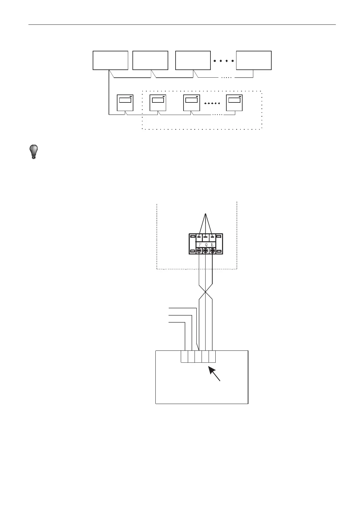
Outdoor unit
#00
Outdoor unit
#01
Outdoor unit
#02
Outdoor unit
#15
Wire Controller
#00
Wire Controller
#01
Wire Controller
#02
Wire Controller
#15
Use PQE connect with each other when several wire-controllers are parallel.
NOTE
Please connect the attached shorted-wires to the corresponding communication port COM(I) or COM(O) in
the main control board of the last parallel unit (dial code ). Directly connect to the last parallel unit if only
one unit is connected.
The wiring procedure and principles are shown in the figure:
P
Black
Q
Gray
E
Ye l lo w
Y
X
Outdoor electric
control box
Communicate with
upper unit(reserved).
Please use
3-cord shield
wire for
connection. The
wire length
depends on the
specific situation
in the installa-
tion.
wire controller
5-bit terminal base
4. OVERVIEW OF WIRED CONTROLLER
Basic conditions of operating the wired controller
1). Applicable range of supply voltage: Input voltage is AC 220V±10%, powered to wire controller by
attached power adapter.
2). Operating environment temperature of wire controller: -15℃~+46℃.
3). Operating RH of wire controller: RH40%~RH90%.
 Loading...