Do you have a question about the Midea MHC-V12W/D2N8-B and is the answer not in the manual?
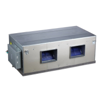
Details unit capacities and visual appearance of the air conditioning units.
Identifies and illustrates the placement of key components within the outdoor unit.
Illustrates the refrigerant and water piping configurations for different operational modes.
Visualizes the path of refrigerant during various operating cycles like heating and cooling.
Explains the conditions and reasons for the system entering a stop state.
Describes how the unit behaves and is managed when in a standby mode.
Details the procedures and logic for initiating unit operation.
Outlines how the unit manages its components during standard running conditions.
Explains various protection mechanisms and error codes to safeguard the unit.
Covers specific operational modes like oil return, defrosting, and fast DHW.
Details the function and importance of temperature sensors in system control.
Shows the physical layout of electrical components within the outdoor unit control box.
Identifies the main printed circuit boards (PCBs) used in the outdoor unit.
Lists all error codes, their meanings, and where they are displayed.
Provides systematic procedures for diagnosing and resolving common issues.
Contains supplementary technical data, such as sensor resistance charts.
| Refrigerant Type | R32 |
|---|---|
| Power Supply | 220-240V, 50Hz |
| Weight (Indoor Unit) | 8.1 kg |
| Refrigerant | R32 |
| Type | Split System |
| Cooling Capacity | 12000 BTU/h |
| Energy Efficiency Ratio (EER) | 3.21 |


