3.2. Indoor Unit Installation
3.2.1 Installation sequence for existing ceiling
3.2.2 Installation sequence for new ceiling
Figure 3.2
Figure 3.5
Figure 3.6
Figure 3.7
Figure 3.3
Figure 3.4
• All bolts should be made from high quality carbon steel (with
galvanized surface or other rust prevention treatment) or stainless
steel.
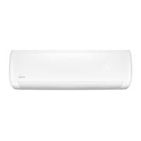
• How the ceiling should be handled will differ with the type of building.
For specific measures, please consult the building and renovation
engineers.
• How the hoisting bolt should be secured depends on the specific
situation, and it must be secure and reliable.
Must maintain the ceiling at a level position.
Original concrete slab structure
Steel framework
Newly set concrete slab structure
Use embedded bolts, and pull bolts.
Directly set and use an angled
steel rod for support.
Set using embedded appliances,
and embedded type of bolts.
Suspension
bolt
Angled rod
for support
Suspension bolt
Knife-type
insertion piece
Sliding-type insertion piece
Reinforced bar
Embedded bolt
(hanging and embedded
bolt for piping)
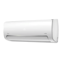
1. Drill 910x910mm square holes into the ceiling based on the layout of the
installation board (accessory 4). See Figure 3.5.
The centre of the ceiling opening should match the centre of the body of the
indoor unit.
Determine the length and outlets of the connecting pipes, water discharge
piping and the electrical wiring.
In order to keep the ceiling level and prevent vibrations, reinforce the
strength of the ceiling when necessary.
Air conditioner body
Ceiling
Position the hole at the
centre of the ceiling opening
Piping
Water discharge pipe
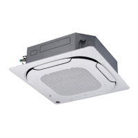
2. Install the hooks in four corners based on the layout for the hooks outlined in
the installation board (accessory 4).
Determine the location on the ceiling of the room or building roof for
mounting, and drill four Φ12mm X 50-55 mm holes. Then embed and set up
the expansion hook anchors (purchased accessory 4) in these holes. See
Figure 3.2.
During the installation of the hooks (purchased accessory 5), make sure
that the concave portion of the hanger corresponds to that of the expansion
hook anchors. Determine the appropriate hook length for installation based
on the ceiling's height. Remove any excess.
Use M10 or W3/8/ bolts for the screws of the mounting hooks.
Take approximately 1/2 of the screw length for the installed hooks as the
excess length.
Top
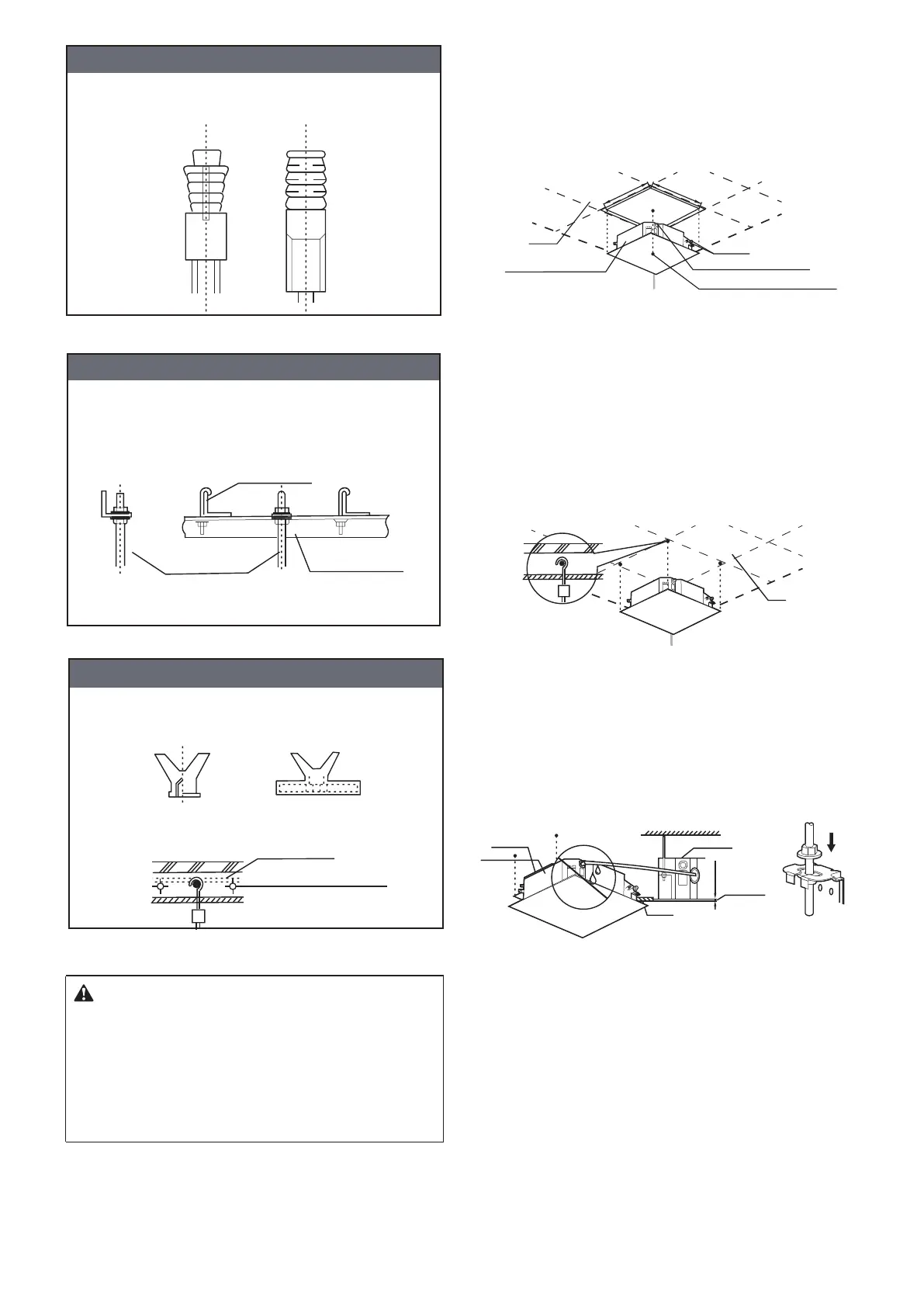
3. Use the hex nuts on the four mounting hooks to adjust and make sure that
the unit body is level.
If the water discharge pipe is slanted, it may cause the water level switch to
malfunction, and water may leak.
Adjust the position of the unit body, and make sure that the gap with the
ceiling is evenly spaced on all four sides of the ceiling, and the base of the
unit body is 10-12 mm into the base of the ceiling.
Once the position of the unit body is adjusted, use the nuts on the mounting
hooks to secure the unit.
1. Refer to Step 2 of the "Installation sequence for existing ceiling". Pre-bury
the hooks in the new ceiling, and make sure that they are strong enough to
bear the weight of the indoor unit, and that the unit will not become loose
when the concrete shrinks.
2. Once you have lifted and mounted the unit, use M6x12 screws (accessory
5) to secure the installation board (accessory 4) on the unit body. Make sure
you verify the size and positions of the opening in the ceiling before you do
so. See Figure 3.8.
Before you mount the unit onto the ceiling, make sure the ceiling is level.
The rest of the procedures are the same as Step 2 of the "Installation
sequence for existing ceiling".
3. Refer to Step 3 of the "Installation sequence for existing ceiling".
4. Remove the installation board (accessory 4).
Air conditioner body
Ceiling
Air conditioner
body
Air
conditioner
frame
Caution
10~12mm
910mm
910mm
5
 Loading...