ES-34
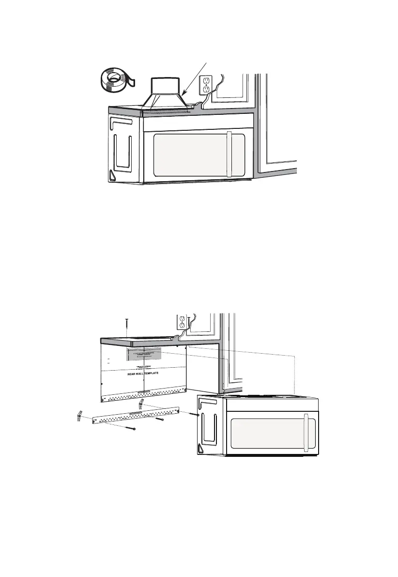
A7. CONEXIÓN DEL CONDUCTO
Conducto de la casa
1. Extienda el conducto de la casa hacia abajo para conectarlo al adaptador de extracción.
2. Selle las juntas del conducto de extracción con cinta adhesiva para conductos de alta
temperatura
B. ESCAPE TRASERO EXTERIOR (conducto horizontal)
REVISIÓN DE LA INSTALACIÓN
B1. Prepare la pared posterior
B2. retiro de la placa del ventilador
B3. Fije la placa de montaje a la pared
B4. Preparar el gabinete superior
B5. Ajuste el ventilador
B6. montaje del horno microondas
12"
4"
NOTE
:
REA
D AND FO
I
T
I
S
V
ERY
LLO
I
W
MPO
T
HE
R
D
TANT
T
O
IRECTIO
IN THE INSTALLAT
I
ON I
NSTRU
CTI
O
N
N
S
S
B
EF
O
RE PR
O
H
T
H T I
W
G N
I
D E
E
C IS
REAR WA
L
L TEM
PL
ATE
.
ll Te
mpl
a
te
serv
es
to p
1
ou
a
. Us
mou
tle
t.
ntin
e
a l
T
h
is
R
ea
g
p
rW
l
a
a
t
e
and
to
loca
te
th
e h
or
iz
o
s
o
n
itio
t
a
n
l e
t
h
xh
e b
au
o
st
t
t
o
m
ioned
to
chec
k tha
t
th
e
t
e
m
pl
at
e
is
p
osit
pl
ark
holes
to
ali
gn wi
th holes
i
n t
he
L
ocat
mounting
RTANT
e and m
:
ate
.
IMPO
E
AT LEA
THE CENT
HE LOCATIO
L
O
C
AT
ERL
INE
ST
.
ONE STUD
ON EI
F
O
ED I S R
E H
T
SP
AC
E
AREA.
MAR
KT
D T
OGGLE
BO
NF
LT
S
O
I
N
R 2 ADD
IT
THE MO
IO
UN
NA
T
ING
L, EV
EN
L
P
LATE
Y
Trim the
re
ar wal
l tem
plat
e along
the
dott
e
d l
ine.
k
h
ole
s to g
ila n w
ith holes
in t
he
moun
tin
g
Loca
te a
n
d
mar
O
RTAN
T
plate.
:IMP
AT LEA
THE CENT
HE
L
O
CATIO
SP
LOCA
T
E
ERLI
N
E.
I
E
N O
D
U
T S E
N O T
S
T
HE
R S
I
D
E
OF
ARE
A.
MA
RK
ACED
T
T
OGG
LE BO
N
F
O
LTS IN
R 2 ADD
ITION
T
H
E
M
OUN
A
TING
L,
EVENL
PLATE
Y
Trim the rear
w
al
l t
e
m
plat
e
a
longt
he dotted
li
ne.
3/8"
TOEDGE
2. L
o
c
c
c
u
a
te
r
a
e
a
t
e
ly
v
nd
el
.
m
a
r
k a
t leas
t
o
d
u
ts
e
n
o
n
th r
o t
f
e l
e
i
ght
si
de of th
e c
ent
e
r
en
il
.
r
It is importa
nt to
use at
l
eas t o
ne
wo
od
sc
rew
mo
ro
unte
d
wa
v
fi
e.
r
M
ml
y
ar
i
k
n
t
a
w
s
o
a
t
ud
d
diti
to sup
p
ona
l, ev
or
en
t the w
ly
s
e
pa
ight
ced
e mic
f
e
o
r
s
i
n
t
he
t
h
s
e
u
m
p
pl
ark
ied to
ed l
o
g
c
g
le bo
l
ati
on
t
s
s
.
.
Wher
e th
er
e is
lo
o
f
a
c
th
3. Dr
a
th
s
i
tio
at
ll
tu
n
h
d
s
ol
d
ri
l
l
a
3/1
6" hol
e fo
r w
ood sc
r
e
ws. F
o
r
h
ol
es
do
,
h t
i
w
p
u
e
a
st
u
d, dril
l
5/8" h
ol
es
fo
r
e bo
no
lts
t lin
.
NO
T
t
oggl
IN
STAL
L
T
H
E
MO
U
NTI
NG
PLATE
AT
4.
R
e
T
m
HI
S
T
D
O
th
IME.
e te
o
v
e
mpla
te fr
omthe rea
r
wall
.
5.R
e
v
ie
w
the In
s
ta
ll
a
t s n I n
o
i
t r
uc
t
ion bo
o
k for your
ins
ta
lla
t
io
n sit
ua
tio
n
.
Darle
vu
el
t
a
ala
ho
japa
raco
ns
ul
tar
la
v
e
rs
i
ón
en
Espa
ño
l.
NOTAS IMPORTANTES:
1. Asegúrese de que los tornillos para el motor del ventilador y la placa del ventilador
estén bien apretados cuando se vuelvan a instalar. Esto ayudará a evitar vibraciones
excesivas.
2. Asegúrese de que el cableado del motor se haya instalado y asegurado correctamente,
y que los cables no estén aplastados.
 Loading...