Page 16
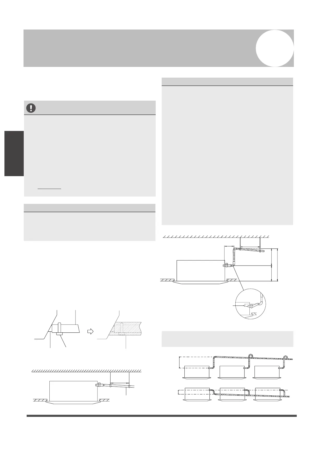
Drainpipe
Installation
NOTE ON DRAINPIPE INSTALLATION
• When using an extended drainpipe, tighten
the indoor connection with an additional
protection tube to prevent it from pulling
loose.
• The drainpipe should slope downward at a
gradient of at least 1/100 to prevent water
from flowing back into the air conditioner.
• To prevent the pipe from sagging, space
hanging wires every 1-1.5m (40-59”).
• If the outlet of the drainpipe is higher than
the body’s pump joint, provide a lift pipe for
the exhaust outlet of the indoor unit. The
lift pipe must be installed no higher than
75cm (29.5”) from the ceiling board and
the distance between the unit and the lift
pipe must be less than 30cm (11.8”).
Incorrect installation could cause water to
flow back into the unit and flood.
• To prevent air bubbles, keep the drain hose
level or slightly tiled up (<75mm / 3”).
Fig. 6.3
NOTE: When connecting multiple drainpipes,
install the pipes as shown in Fig 6.4.
0-53cm
(20.8”)
≥10cm
(4”)
Fig. 6.4
The drainpipe is used to drain water from the
unit. Improper installation may cause unit and
property damage.
CAUTION
• Insulate all piping to prevent condensation,
which could lead to water damage.
• If the drainpipe is bent or installed
incorrectly, water may leak and cause a
malfunction of the water- level switch.
• In HEAT mode, the outdoor unit will
discharge water. Ensure that the drain hose
is placed in an appropriate area to avoid
water damage and slippage due to frozen
drain water.
• DO NOT pull the drainpipe forcefully as this
could cause it to disconnect.
NOTE ON PURCHASING PIPES
This installation requires a polyethylene tube
(outside diameter = 3.7-3.9cm, inside diameter
= 3.2cm), which can be obtained at your local
hardware store or from your dealer.
Indoor Drainpipe Installation
Install the drainpipe as shown in Figure 6.2.
1. Cover the drainpipe with heat insulation to
prevent condensation and leakage.
2. Attach the mouth of the drain hose to the
unit’s outlet pipe. Sheath the mouth of the
hose and clip it rmly with a pipe clasp.
(Fig 6.1)
Drainpipe
connecting port
Drain hose
Metal clamp
Insulation
Fig. 6.1
Drainpipe Installation
6
Downward slope
1/100
1-1.5m
(39-59”)
Fig. 6.2
≤75cm
(29.5”)
1 - 1.5m
(39-59”)
0 - 75mm
(3”)
≤30cm (11.8”)
≤53cm
(20.8”)
22cm
(8.6”)
 Loading...