11
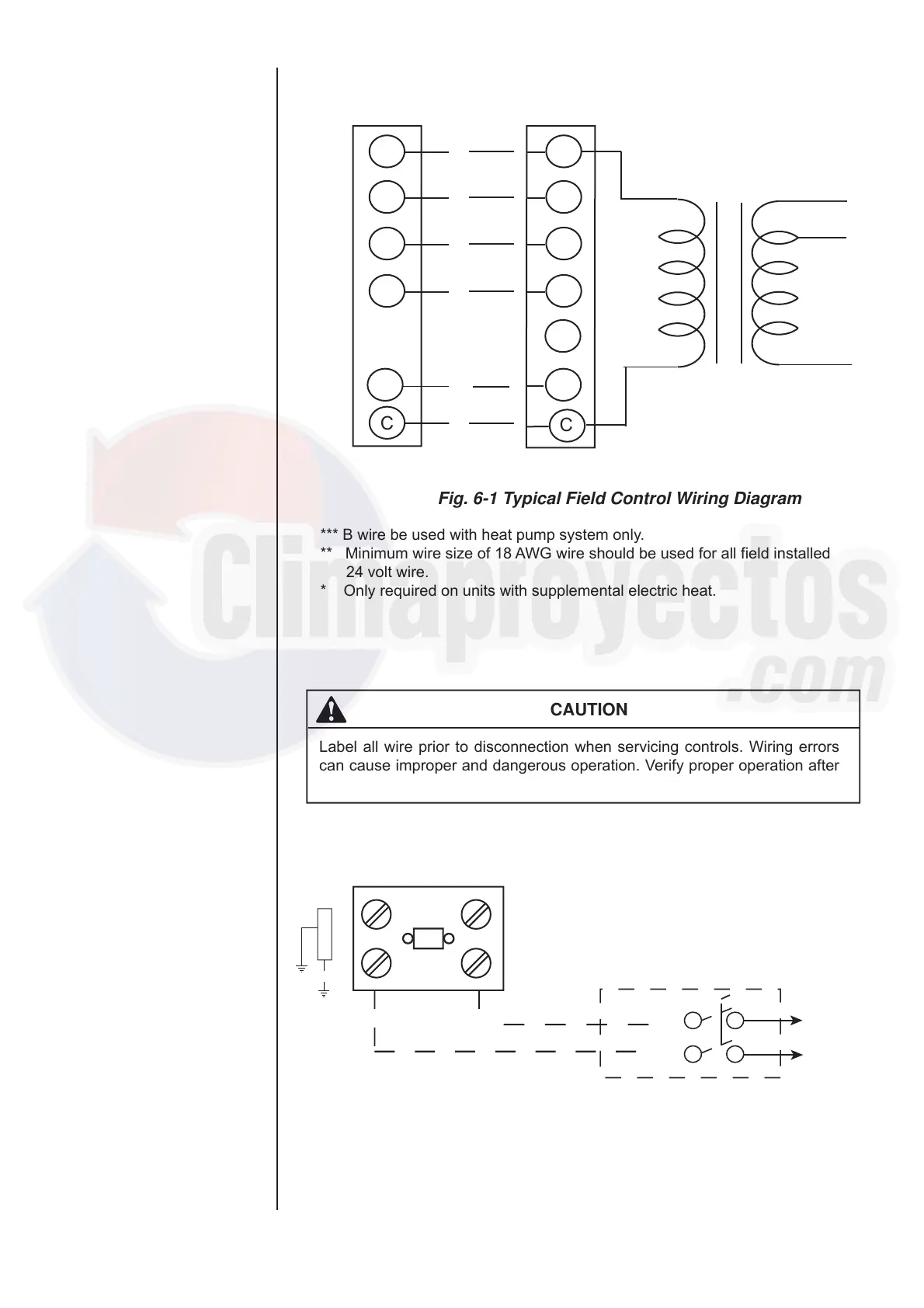
CAUTION
Label all wire prior to disconnection when servicing controls. Wiring errors
can cause improper and dangerous operation. Verify proper operation after
servicing.
CONTACTOR
GROUND
LUG
Refer to electrical data tables
to size the disconnect
Field-supplied disconnect
Single
phase
power
supply
Fig. 6-2 Typical Field Power Wiring Diagram
R
G
Y
W
C
R
G
Y
W
1
W
2
C
24 volt
transformer
THERMOSTAT
UNIT CONTROL BOARD
THERMINAL STRIP
*** B wire be used with heat pump system only.
** Minimum wire size of 18 AWG wire should be used for all field installed
24 volt wire.
* Only required on units with supplemental electric heat.
Fig. 6-1 Typical Field Control Wiring Diagram
B B
240V
208V
COM
***
*
**
 Loading...