The resetting phenomenon often occurs during operation because the instantaneous voltage of the main chip is less than 4.5V. To resolve this, check the indoor PCB and fan motor.
E
Erik BrewerAug 17, 2025
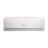
What to do if my Midea MSG-05CR shows an EEROM error and the indoor PCB is defective?
J
James BrooksAug 18, 2025
If your Midea Air Conditioner displays an EEROM error and the indoor PCB is defective, replace the indoor PCB.