Do you have a question about the Midea MSMACU-18HRFN8-QRD0GW and is the answer not in the manual?
General safety measures, operation, and maintenance guidelines for the unit.
Procedures and checks for servicing units with flammable refrigerants safely.
Table detailing indoor and outdoor unit model compatibility and specifications.
Specifications for connection pipe length, elevation limits, and additional refrigerant.
Diagrams illustrating indoor and outdoor unit electrical connections and PCB layouts.
Explanation of various functions displayed on the unit's display panel.
Details on built-in safety mechanisms like compressor protection and sensor redundancy.
Overview of fundamental operating modes and controls like Fan Mode, Cooling, and Heating.
Procedure for leak testing and evacuation of the system before initial operation.
Step-by-step guide for charging the system with the correct amount of refrigerant.
Procedures for collecting refrigerant and preparing the system for re-installation.
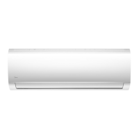
Physical dimensions of the indoor unit for different models.
Step-by-step instructions for removing the front panel of the indoor unit.
Procedures for safely disassembling and removing electrical components of the indoor unit.
Instructions for removing the evaporator from the indoor unit.
Steps to remove the fan motor and fan assembly from the indoor unit.
Procedure for removing the step motor from the indoor unit.
Table correlating outdoor unit models with panel plates and PCB boards.
Instructions for disassembling various panel plates of the outdoor unit.
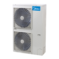
Physical dimensions of outdoor units for different panel plates.
Procedures for disassembling electrical components, including PCB boards.
Steps to remove the fan assembly from the outdoor unit.
Instructions for removing the fan motor from the outdoor unit.
Procedure for removing the sound blanket from the outdoor unit.
Steps for safely removing the four-way valve, especially for heat pump models.
Detailed procedure for removing the compressor, including safety precautions.
Essential safety warnings and precautions before performing troubleshooting procedures.
Common error codes displayed by the indoor unit and their corresponding information.
A form for recording customer complaints, product information, and failure descriptions.
Procedure for accessing and displaying unit information codes via the remote controller.
Guidance for diagnosing and resolving issues when no specific error code is displayed.
A table mapping error codes to required part replacements for quick maintenance.
Detailed diagnosis and solutions for specific error codes encountered by the unit.
Methods for checking sensor resistance and compressor winding resistance.
Table of resistance values for temperature sensors at various Celsius and Fahrenheit temperatures.
Table of resistance values for the TP temperature sensor at various temperatures.
Cooling and heating charts showing pressure values for different refrigerants and conditions.
| Type | Inverter |
|---|---|
| Capacity (BTU) | 18000 |
| Power Supply | 220-240V, 50Hz |
| Refrigerant | R32 |
| Cooling Capacity | 5.3 kW |