VC Pro VRF 50/60Hz
144
Midea VC Pro Series Engineering Data Book
2.1.3 Master and slave unit positioning
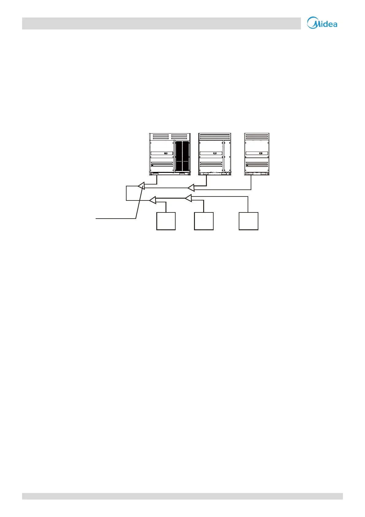
In systems with multiple outdoor units, the units should be placed in order from largest capacity unit to smallest capacity
unit. The largest capacity unit must be placed on the first branch, and be set as the master unit, while the others should be
set as slave units. Refer to the VC Pro Service Manual, Part 4 for details of how to set units as master/slave.
The example in Figure 3-2.4 illustrates the placing of units in a 66HP combination:
Place the 28HP unit on the first branch and set it as the master unit.
Place the 22HP and 16HP units on the next branches and set them as slave units.
Figure 3-2.4: Positioning of master and slave units
2.1.4 Base structures
Outdoor unit base structure design should take account of the following considerations:
A solid base prevents excess vibration and noise. Outdoor unit bases should be constructed on solid ground or on
structures of sufficient strength to support the units’ weight.
Bases should be at least 200mm high to provide sufficient access for installation of piping.
Either steel or concrete bases may be suitable.
A typical concrete base design is shown in Figure 3-2.5. A typical concrete specification is 1 part cement, 2 parts sand
and 4 parts crushed stone with Φ10mm steel reinforcing bar. The edges of the base should be chamfered.
To ensure that all contact points are equally secure, bases should be completely level. Base design should ensure that
the points on the units’ bases designed for weight-bearing support are fully supported. Bolt spacings should be as per
Figure 3-2.6 and Table 3-2.1.
C(16HP)B(22HP)A(28HP)
Indoor
unit A
Indoor
unit B
Indoor
unit C
First outdoor
branch joint
Outdoor units
(66HP)
 Loading...