EasyManua.ls Logo

Midea SEL-KFR53GW/Y-A(B) User Manual

Midea SEL-KFR53GW/Y-A(B)
42 pages
To Next Page IconTo Next Page
Page #1 background imageLoading...
Page #1 background image
0
Website: www.mideaaircon.com
Service manual
CAUTION
- BEFORE SERVICING THE UNIT, READ THE SAFETY
- PRECAUTIONS IN THIS MANUAL.
- ONLY FOR AUTHORIZED SERVICE PERSONNEL.
MODELS:
EL-KF20GW/N2Y-A(B) EL-KFR20GW/N2Y-A(B) EL-KF26GW/N2Y-A(B) EL-KFR26GW/N2Y-A(B)
EL-KF36GW/N2Y-A(B) EL-KFR36GW/N2Y-A(B) EL-KF50GW/N2Y-A(B) EL-KFR50GW/N2Y-A(B)
EL-KF61GW/N2Y-A(B) EL-KFR61GW/N2Y-A(B) EL-KF70GW/N2Y-A(B) EL-KFR70GW/N2Y-A(B)
EL-KFR20GW/N1Y-A(B) EL-KFR26GW/N1Y-A(B) EL-KFR36GW/N1Y-A(B)
EL-KF20GW/Y-A(B) EL-KFR20GW/Y-A(B) EL-KF26GW/Y-A(B) EL-KFR26GW/Y-A(B)
EL-KF32GW/Y-A(B) EL-KFR32GW/Y-A(B) EL-KF36GW/Y-A(B) EL-KFR36GW/Y-A(B)
EL-KF50GW/Y-A(B) EL-KFR50GW/Y-A(B) EL-KF61GW/Y-A(B) EL-KFR61GW/Y-A(B)
EL-KF70GW/Y-A(B) EL-KFR70GW/Y-A(B) EL-KF90GW/Y-A(B) EL-KFR90GW/Y-A(B)
EL-KF90GW/SY-A(B) EL-KFR90GW/SY-A(B) AU-KF61GW/Y-A(B) AU-KFR61GW/Y-A(B)
AU-KF70GW/Y-A(B) AU-KFR70GW/Y-A(B) AU-KF85GW/Y-A(B) AU-KFR85GW/Y-A(B)
EL1-KF20GW/Y-A(B) EL1-KFR20GW/Y-A(B) EL1-KF26GW/Y-A(B) EL1-KFR26GW/Y-A(B)
EL1-KF32GW/Y-A(B) EL1-KFR32GW/Y-A(B) EL1-KF20GW/N2Y-A(B) EL1-KFR20GW/N2Y-A(B)
EL1-KF26GW/N2Y-A(B) EL1-KFR26GW/N2Y-A(B) EL1-KF35GW/N2Y-A(B) EL1-KFR35GW/N2Y-A(B)
EL-KT3F53GW/Y-T2 EL-KT3F53GW/Y-T1 EL-KT3FR53GW/Y-T1
EL-KT3F70GW/Y-T2 EL-KT3F70GW/Y-T1 EL-KT3FR70GW/Y-T1
SEL-KF20GW/Y-A(B) SEL-KFR20GW/Y-A(B) SEL-KF26GW/Y-A(B) SEL-KFR26GW/Y-A(B)
SEL-KF32GW/Y-A(B) SEL-KFR32GW/Y-A(B) SEL-KF53GW/Y-A(B) SEL-KFR53GW/Y-A(B)
SEL-KF61GW/Y-A(B) SEL-KFR61GW/Y-A(B) SEL-KF70GW/Y-A(B) SEL-KFR70GW/Y-A(B)
SEL1-KF26GW/Y-A(B) SEL1-KFR26GW/Y-A(B) SEL1-KF36GW/Y-A(B) SEL1-KFR36GW/Y-A(B)
Question and Answer IconNeed help?

Do you have a question about the Midea SEL-KFR53GW/Y-A(B) and is the answer not in the manual?

Midea SEL-KFR53GW/Y-A(B) Specifications

General IconGeneral
RefrigerantR410A
TypeSplit-type Air Conditioner
Cooling Capacity5300W
Heating Capacity5.6 kW
Power Supply220-240V, 50Hz
Compressor TypeRotary Compressor

Summary

CAUTION

MODELS

PREFACE

1.1 SAFETY PRECAUTIONS

Essential safety guidelines for servicing, including power disconnection and insulation testing.

1.2 INSULATION RESISTANCE TEST

Procedure for verifying electrical insulation to prevent shock hazards after servicing.

1.3 FEATURES

Overview of the air conditioner's key functions and features, such as self-diagnosis and protection.

1.4 CONTROL LOCATIONS

Identifies and explains the locations and functions of indoor unit and remote control elements.

1.5 OUTSIDE DIMENSIONS

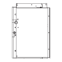
Provides detailed physical dimensions for various indoor and outdoor unit models for installation planning.

INSTALLATION

2.1 TOOLS NEEDED FOR INSTALLATION

Lists all necessary tools required for the correct installation of the air conditioning unit.

2.2 ITEMS REQUIRED FOR INSTALLING THE UNIT

Lists essential accessories and materials needed for unit installation beyond tools.

2.3 INSTALLATION OF INDOOR UNIT AND OUTDOOR UNIT

Step-by-step instructions and requirements for correctly mounting indoor and outdoor units.

2.4 FLARING WORK AND CONNECTION OF PIPING

Detailed procedure for creating flared pipe ends and connecting refrigerant lines to prevent leaks.

2.5 CONNECTING THE CABLE BETWEEN INDOOR UNIT AND OUTDOOR UNIT

Guidelines for safely and correctly connecting electrical cables between indoor and outdoor units.

2.6 CHECKING THE DRAINAGE AND FORMING THE PIPING

Procedures for verifying drainage system functionality and proper pipe formation to prevent water issues.

2.7 AIR PURGING

Method for removing air and moisture from the refrigerant system using a vacuum pump.

2.8 TEST RUNNING

Steps to follow for a successful test run of the air conditioner after installation.

TROUBLE SHOOTING GUIDE

3.1 Refrigeration Cycle Diagram

Visual representation of the refrigeration cycle for both cooling-only and reverse cycle air conditioners.

3.2 TROUBLE SHOOTING GUIDE

Comprehensive guide to diagnose and resolve common air conditioner operational issues and error codes.

WIRING DIAGRAM

4.1 Wiring diagram for indoor units.

Electrical schematics illustrating the internal wiring for various indoor unit models.

4.2 Wiring diagram for outdoor units.

Electrical schematics illustrating the internal wiring for various outdoor unit models.

EXPLODED VIEWS

REPLACEMENT PARTS LIST

SPECIFICATIONS

MODEL CHECK LIST

Related product manuals