EasyManuals Logo

Midea V6R Series User Manual

Midea V6R Series
131 pages
To Next Page IconTo Next Page
To Previous Page IconTo Previous Page
Page #84 background imageLoading...
Page #84 background image
V6R VRF 50/60Hz
139
Part 3
-
System Design and Installation
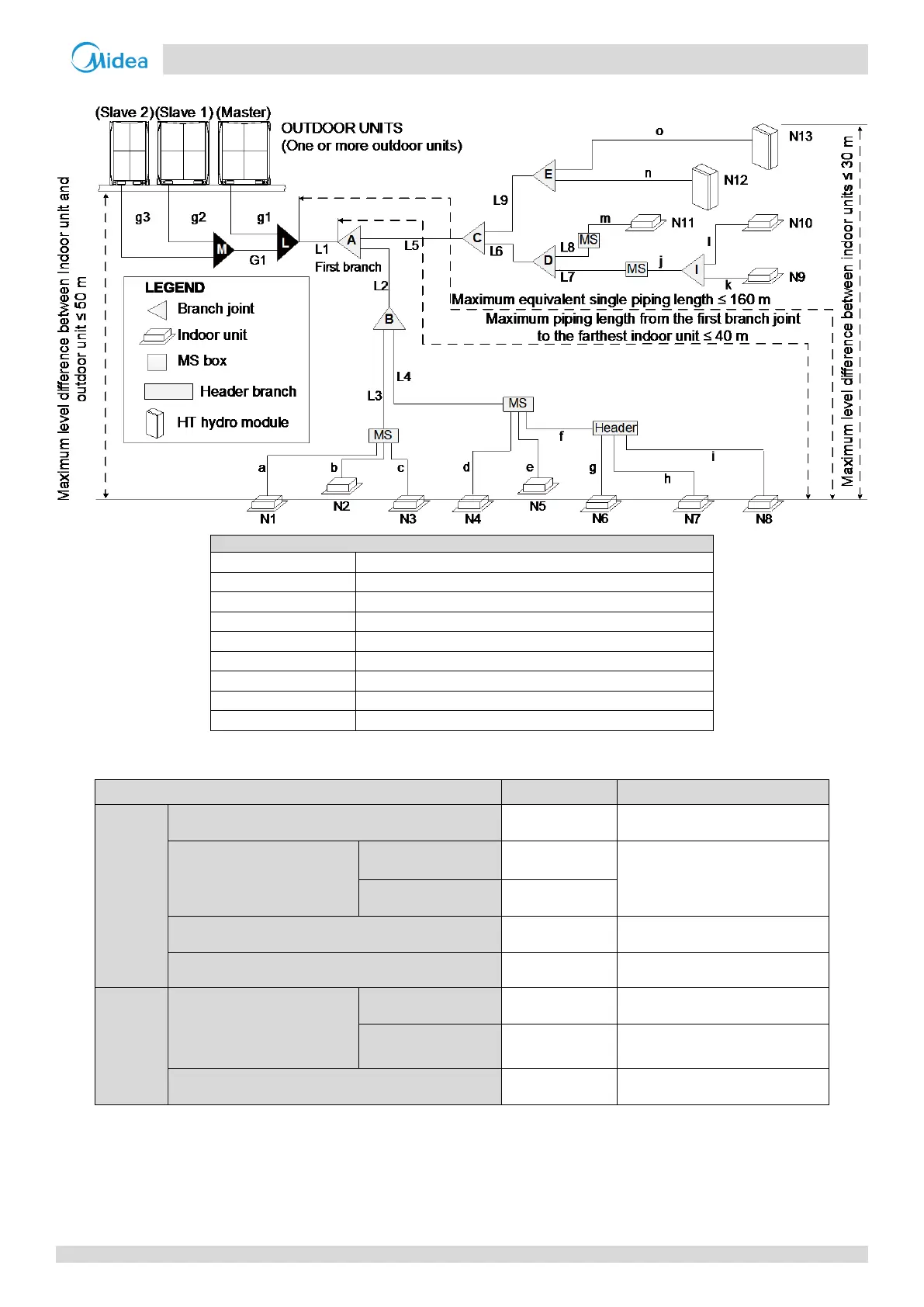
Figure 3-4.3: Permitted refrigerant piping lengths and level differences
Legend
g1, g2, g3, G1
Main pipe
L, M
Outdoor unit connection pipe
L1
Outdoor unit branch joint
L2 to L9
Main pipe
A to E
Indoor unit main pipe
I
Branch joint between main pipe and MS or HT hydro module
a to o
Branch joint between MS and indoor unit
N1 to N11
VRF indoor unit
N12, N13
HT Hydro module
Table 3-4.4: Summary of permitted refrigerant piping lengths and level differences
Permitted values
Piping in Figure 3-4.5
Piping lengths
Total piping length
1
≤ 600 m
L1+ 2 x Ʃ{L2 to L9} + Ʃ{a to o}
Piping between farthest VRF
indoor unit or HT hydro
module and first indoor
branch joint
2
Actual length
≤ 135 m
L1 + L2 + L4 + f + i
Equivalent length
≤ 160 m
Piping between farthest VRF indoor unit or HT hydro
module and first branch joint
3
≤ 40 m
L2 + L4 + f + i
Piping between outdoor unit and outdoor branch joint
10 m
g1 10 m; g2+G1 10 m;
g3 + G1 10 m
Level differences
Largest level difference
between VRF indoor unit or
HT hydro module and
outdoor unit
4
Outdoor unit is above
≤50 m
Outdoor unit is
below
40 m
Largest level difference between VRF indoor units
or HT hydro module
≤ 30 m
Notes:
1. Refer to Requirement 1, above.
2. Refer to Requirement 2, above.
3. Refer to Requirement 3, above.
4. Refer to Requirement 4, above.

Other manuals for Midea V6R Series

Questions and Answers:

Question and Answer IconNeed help?

Do you have a question about the Midea V6R Series and is the answer not in the manual?

Midea V6R Series Specifications

General IconGeneral
BrandMidea
ModelV6R Series
CategoryAir Conditioner
LanguageEnglish

Related product manuals