Do you have a question about the Midea V6R VRF Series and is the answer not in the manual?
Details capacities and types of VRF indoor and outdoor units, including capacity ranges.
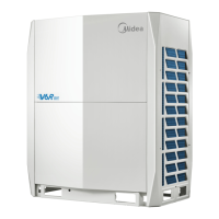
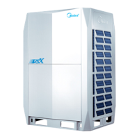
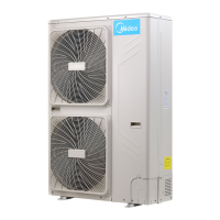
Visual representations and descriptions of various indoor and outdoor unit types.
Explains factory-recommended combinations of outdoor units based on system capacity.
Outlines limitations and rules for indoor and outdoor unit combination ratios.
Illustrates the location of key functional components within the outdoor units.
Presents detailed piping diagrams for different outdoor unit models.
Illustrates refrigerant flow during various operating modes like cooling and heating.
Provides a flowchart detailing the activation logic of various system controls.
Explains the conditions and component controls during system stop operations.
Details the crankcase heater control function during standby mode.
Describes the startup sequence and compressor startup delay control procedures.
Details component control during normal cooling, heating, and simultaneous operations.
Explains various protection mechanisms like high pressure, low pressure, and temperature controls.
Covers special control functions like oil return and defrosting operations.
Details other control modes such as overload, pump-down, and snow-blowing control.
Explains the function of PCB switches and their settings for outdoor unit configuration.
Details the switch settings for MS01 and MS04-12 mode selection boxes.
Shows the layout and components within the outdoor unit's electric control box.
Identifies ports and components on the outdoor unit's main PCB.
Describes the layout, components, and functions of the data transfer module.
Details the ports and LED indicators of the compressor inverter module.
Shows the ports and connections for the fan module.
Identifies ports and switches on the MS01 and MS04-12 main PCBs.
Provides detailed wiring diagrams for outdoor units and MS boxes.
Lists all error codes, their content, remarks, and manual restart requirements.
Provides step-by-step troubleshooting procedures for common outdoor unit errors.
Offers troubleshooting steps for errors related to the Mode Selection Box.
Contains reference data such as temperature sensor resistance and pressure sensor voltage characteristics.
| Type | VRF (Variable Refrigerant Flow) |
|---|---|
| Refrigerant | R410A |
| DC Inverter Compressor | Yes |
| Energy Efficiency Ratio (EER) | Up to 4.0 (Varies by model) |
| Indoor Unit Noise Level | 26-45 dB(A) (Varies by indoor unit type and model) |
| Operating Temperature Range (Cooling) | -5°C to 48°C |
| Control System | Centralized Controller, Individual Controllers, BMS Integration |
| Communication | MODBUS |
| Indoor Unit Types | Cassette, wall-mounted, ducted, ceiling-concealed, floor-standing |
| Outdoor Unit Dimensions (Varies by Model) | Varies significantly by model. Refer to specific model documentation. |
| Indoor Unit Dimensions (Varies by Model) | Varies significantly by model and type. Refer to specific model documentation. |