Part 5
-
Electrical Components and Wiring Diagrams
Table 5-4.2: 14-18HP compressor inverter module ports
Three phase power input of L1
380V AC between L1/L2 and L3;
Three phase power input of L2
380V AC between L1/L2 and L3;
Three phase power input of L3
380V AC between L1/L2 and L3;
Three phase output of the inverter ,connected to the
compressor
Three phase output of the inverter ,connected to the
compressor
Three phase output of the inverter ,connected to the
compressor
Program port for main chip
Program port for parameters
Communication port to Main PCB
High pressure switch connection
Power supply terminal for DC fan inverter module
AC power supply for inverter module
Power supply terminal for DC fan inverter module (P,N)
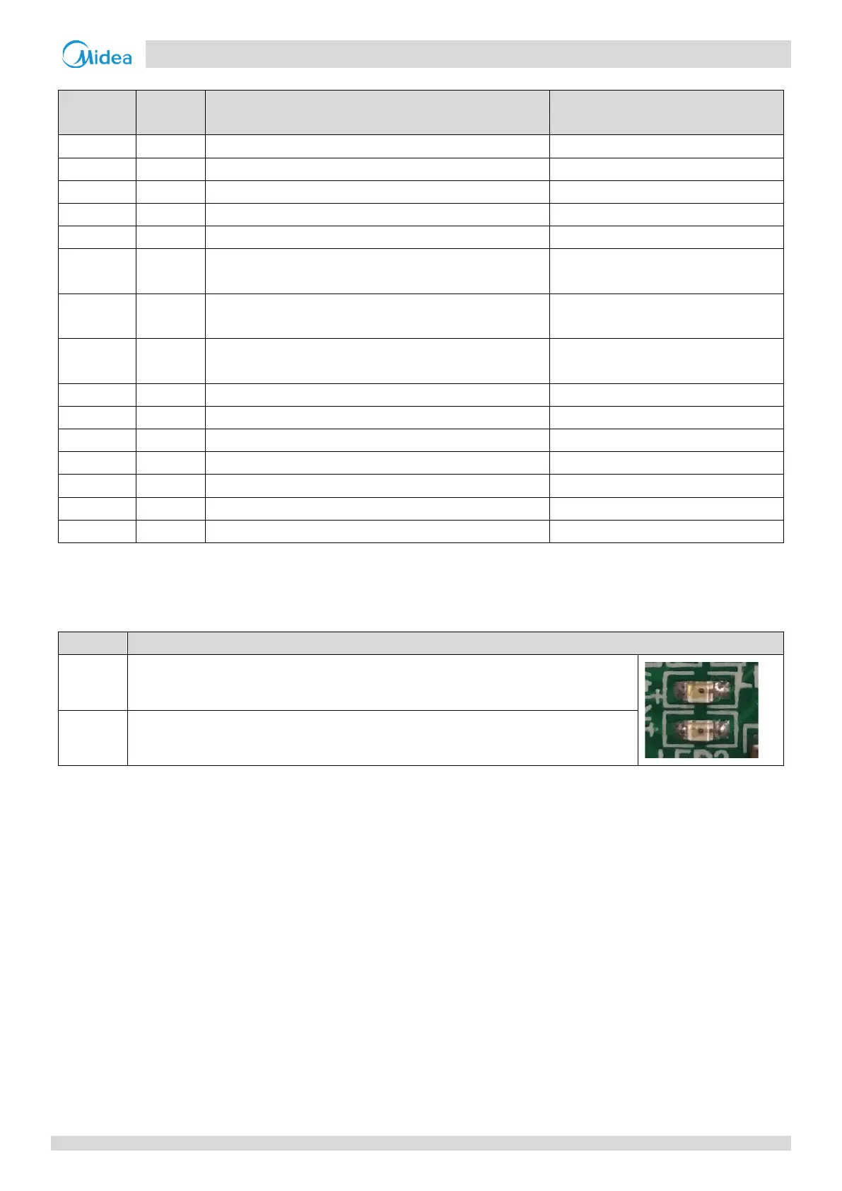
Table 5-4.1: LED indicators LED1 and LED2
LED indicator function and status
Inverter module operating indicator. Continuously on if the compressor is running normally and
flashing if an inverter module error has occurred
1
.
Inverter module error indicator. Continuously on if an inverter module error has occurred
1
.
Note:
1. If an inverter module error occurs, refer to Part 6, “H4 Troubleshooting”. The error code is displayed on the digital display.

 Loading...